
Ford Upfitter Switches Wiring Diagram
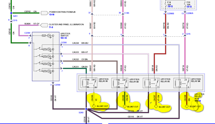
So, you're looking to add some serious functionality to your Ford truck or van with the upfitter switches? Excellent choice! These factory-installed switches are a fantastic way to cleanly integrate aftermarket accessories like auxiliary lights, winches, plows, or anything else that needs a dedicated power source. But before you start hacking away at your vehicle's wiring, it's crucial to understand the upfitter switches wiring diagram. This article is your guide to deciphering that diagram, ensuring you can safely and effectively connect your accessories.
Why This Diagram Matters
Having a clear understanding of the upfitter switch wiring diagram is paramount for several reasons:
- Safe Installation: Incorrect wiring can lead to short circuits, blown fuses, or even damage to your vehicle's electrical system. A good diagram helps you avoid these costly mistakes.
- Efficient Troubleshooting: If an accessory connected to an upfitter switch malfunctions, the diagram is your first line of defense in diagnosing the problem.
- Understanding Your Vehicle: It's a great way to learn how your vehicle's electrical systems are designed and how various components interact.
- Customization and Expansion: Once you understand the basics, you can confidently modify or expand your accessory setup.
- Repairs: If any issues occur with the upfitter switches themselves, the diagram becomes invaluable for tracing circuits and pinpointing the source of the problem.
Key Specs and Main Parts
The upfitter switch system typically consists of the following main components:
- Upfitter Switch Pack: This is the physical switch assembly located in the cab. It contains multiple switches (usually 4 or 6) that control the power to your accessories.
- Relays: Each switch usually controls a dedicated relay. A relay is an electromechanical switch that allows a low-current circuit (the switch itself) to control a high-current circuit (the accessory). This protects the switch from being overloaded. The relays are generally located in the engine compartment.
- Fuses: Each relay circuit is protected by a fuse. These fuses protect the wiring and the accessories from overcurrent conditions.
- Wiring Harness: A pre-wired harness connects the switch pack to the relays, fuses, and the vehicle's power distribution system.
- Power Source: The upfitter switches typically draw power directly from the vehicle's battery.
- Grounding Points: Proper grounding is essential for any electrical circuit to function correctly. The diagram will show the designated grounding points for the upfitter switch system.
Typical specifications to consider are the amperage rating of each switch/relay circuit and the gauge (thickness) of the wiring used. Larger gauge wire can handle more current. For example, a typical upfitter switch might be rated for 25 amps, meaning it can safely handle accessories that draw up to 25 amps.
Symbols – Deciphering the Diagram
Understanding the symbols used in the wiring diagram is crucial. Here are some common symbols and their meanings:
- Solid Lines: Represent wires. The thickness of the line might indicate the wire gauge.
- Dashed Lines: May indicate a shielded wire or a connection to a component that's physically distant.
- Circles: Often represent terminals or connection points.
- Rectangles: Can represent various components like relays, switches, or fuses. Specific markings within the rectangle will identify the component (e.g., "RELAY 1" or "FUSE 5").
- Ground Symbol (usually a downward-pointing triangle or a series of horizontal lines): Indicates a connection to the vehicle's chassis ground.
- Battery Symbol: Represents the vehicle's battery, the primary power source.
- Fuse Symbol (a squiggly line inside a rectangle or circle): Represents a fuse. The diagram should also indicate the fuse amperage rating.
- Color Codes: Wires are often color-coded. The diagram will have a key that identifies which color corresponds to which wire (e.g., "RD" for red, "BK" for black, "WH" for white, etc.). Using correct color code will maintain consistency.
Color coding is extremely important. Ford uses a standard set of color codes for their wiring. Matching the wire colors in the diagram to the actual wires in your vehicle is a primary method of verifying that you're connecting to the correct circuit.
How It Works
The upfitter switch system works by providing a convenient and safe way to control power to aftermarket accessories. Here's the basic principle:
- When you flip an upfitter switch to the "ON" position, it completes a low-current circuit that energizes the corresponding relay.
- The energized relay acts as a switch, closing a high-current circuit that connects the accessory to the vehicle's battery.
- The accessory receives power and operates.
- When you flip the switch to the "OFF" position, the relay is de-energized, breaking the high-current circuit and cutting power to the accessory.
This setup protects the upfitter switch from being overloaded. The relay handles the high current draw of the accessory, while the switch only controls the low-current circuit that energizes the relay.
Real-World Use – Basic Troubleshooting Tips
Here are some basic troubleshooting tips when working with upfitter switches:
- Accessory Not Working: The first step is to check the fuse for that particular switch circuit. Use a multimeter to test the fuse for continuity.
- Switch Not Lighting Up: Some upfitter switches have indicator lights. If the light isn't working, it could indicate a problem with the switch itself or with the power supply to the switch.
- Relay Clicking but Accessory Not Working: This could indicate a problem with the relay itself, the wiring between the relay and the accessory, or the accessory itself. Use a multimeter to check for voltage at the accessory connector when the relay is energized.
- Short Circuit: If a fuse blows repeatedly, it indicates a short circuit. Carefully inspect the wiring for any signs of damage or exposed wires.
- Grounding Issues: Ensure all grounding points are clean and securely connected. A poor ground can cause intermittent problems or prevent the accessory from working at all.
Safety – Handle with Care!
Working with automotive electrical systems can be dangerous if proper precautions are not taken. Always disconnect the negative terminal of the vehicle's battery before working on any electrical components. This is crucial!
Be particularly careful when working with the battery and the wiring connected to the upfitter switches. The battery can deliver a high current, which can cause severe burns or even death. Always use insulated tools and wear appropriate safety glasses.
When making connections, ensure that they are secure and properly insulated. Use heat shrink tubing or electrical tape to protect exposed wires. Avoid using crimp connectors without proper tools. They can corrode and fail over time. If using quick splices ("vampire taps"), use with caution as they can damage the wiring.
Pay close attention to the amperage rating of the fuses. Never replace a fuse with one that has a higher amperage rating. This can overload the circuit and cause a fire.
It is always recommend you consult a professional if you are unsure about any aspect of the upfitter switch wiring.
We have a detailed Ford Upfitter Switch Wiring Diagram available for download. This diagram will provide you with the specific wiring configuration for your vehicle model, helping you install and troubleshoot your upfitter switches with confidence.