
Ford Voltage Regulator Wiring Diagram
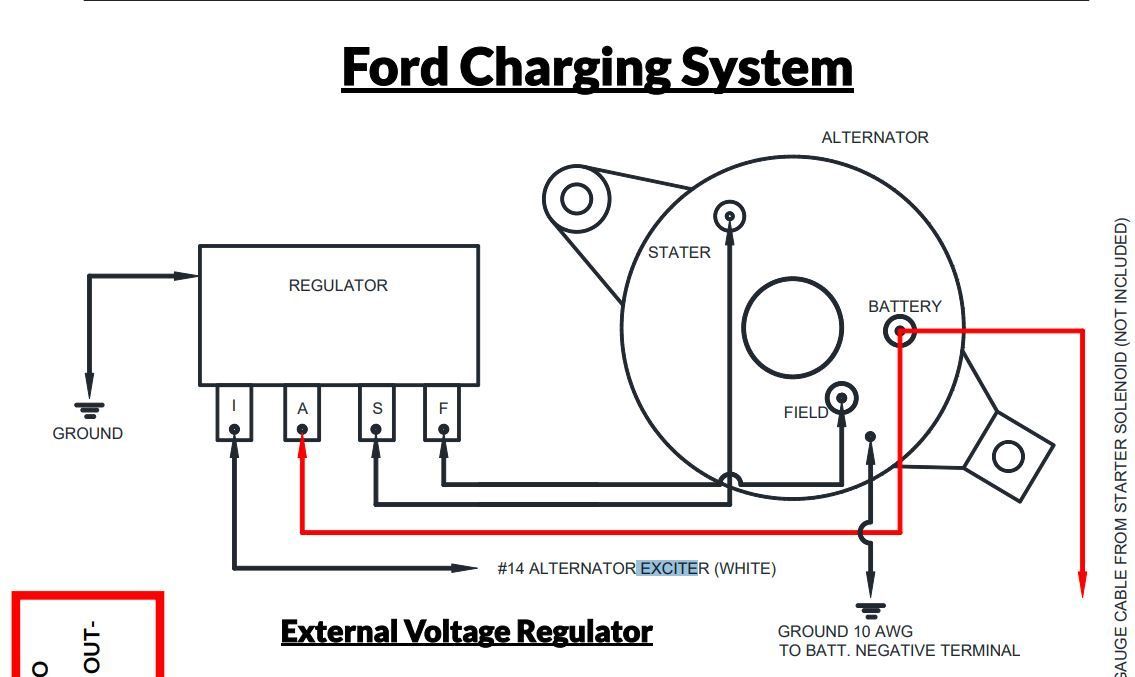
For the seasoned DIY mechanic tackling vintage Fords or even modifying newer charging systems, understanding the Ford voltage regulator wiring diagram is absolutely crucial. This isn't just about tracing wires; it's about understanding how the entire charging system functions, allowing you to diagnose problems, perform repairs correctly, and even potentially upgrade your system with confidence. We have included the file for you to download at the end of this article.
Why Bother with the Diagram?
Think of the wiring diagram as the blueprint of your vehicle's charging system. It's invaluable for several reasons:
- Troubleshooting: When your battery isn't charging correctly, the diagram helps you isolate the fault – is it the alternator, the regulator, or a wiring issue?
- Repairing or Replacing Components: Correctly connecting a new voltage regulator or alternator requires knowing exactly where each wire goes.
- Modifications: Upgrading to a higher-output alternator or converting to a one-wire system necessitates a solid understanding of the existing wiring to avoid damaging components.
- Learning the System: Even if you don't have a problem, studying the diagram helps you understand how the charging system works, empowering you to make informed decisions about maintenance and upgrades.
Key Specs and Main Parts
Before diving into the diagram, let's review the key components and terminology. We'll focus primarily on the older electro-mechanical regulators, as they are often the focus of restoration and modification projects. Although newer vehicles use electronic regulators, understanding the older systems is a valuable learning experience.
Components:
- Alternator: The heart of the charging system, converting mechanical energy from the engine into electrical energy. It contains the stator (stationary windings), the rotor (rotating magnetic field), and diodes (rectifiers that convert AC to DC).
- Voltage Regulator: This component controls the alternator's output voltage, preventing overcharging and protecting the battery and other electrical components. Older systems use electro-mechanical regulators, while newer systems use solid-state electronics.
- Battery: Stores electrical energy and provides power to start the engine and run accessories when the alternator isn't producing enough power.
- Ammeter/Voltmeter: Provides a visual indication of the charging system's performance. An ammeter shows current flow (charge or discharge), while a voltmeter displays voltage.
- Wiring Harness: A bundle of wires that connects the various components of the charging system.
Key Specs to Consider:
- Voltage: Most automotive systems operate at 12 volts DC.
- Amperage (Current): The alternator's output capacity is measured in amps. Higher-output alternators can provide more power for accessories.
- Wire Gauge: The thickness of the wires is crucial for handling the current flow. Thicker wires are needed for higher amperage circuits.
Decoding the Ford Voltage Regulator Wiring Diagram
The wiring diagram is a symbolic representation of the electrical circuit. Understanding these symbols is key to interpreting the diagram correctly.
Lines:
Lines represent wires or conductors. A solid line typically indicates a direct wire connection, while a dashed line might indicate a ground connection or a connection that exists only under certain conditions (e.g., when a switch is activated).
Colors:
Wire colors are often indicated on the diagram using abbreviations (e.g., "BK" for black, "RD" for red, "GN" for green). These colors are standardized within Ford's wiring conventions. Using the correct color wires during repairs is highly recommended for maintainability and future troubleshooting.
Icons and Lettering:
Here are some common icons and letter designations you'll encounter:
- ALT: Alternator
- REG: Voltage Regulator
- BAT: Battery
- GND: Ground
- "S" or "Sense" terminal: This terminal senses the voltage at a specific point in the system (usually the battery or main power distribution point) and uses this information to regulate the alternator's output.
- "A" or "Stator" terminal: Connects to the stator winding inside the alternator.
- "F" or "Field" terminal: Connects to the rotor field winding inside the alternator. The regulator controls the current flow to this winding to regulate the alternator's output.
- Resistors: Zigzag lines represent resistors, which limit current flow.
- Capacitors: Parallel lines represent capacitors, which store electrical energy.
Common Ford Regulator Terminals:
These terminals are commonly found on Ford regulators, especially the older electro-mechanical types:
- "A": Connected to the alternator's stator terminal (the AC output before rectification).
- "F": Connected to the alternator's field winding.
- "S": Voltage sense wire, connected to the battery or a point of constant voltage.
- "I": Ignition or "accessory" wire, providing power to the regulator when the ignition is on.
How the Charging System Works
Understanding the flow of electricity is key to using the diagram effectively.
- When the engine starts, the alternator begins to spin, driven by a belt connected to the crankshaft.
- The rotating rotor inside the alternator generates a magnetic field.
- This magnetic field induces an AC voltage in the stator windings.
- The diodes rectify the AC voltage to DC voltage.
- The voltage regulator monitors the system voltage and adjusts the current flowing through the field winding of the alternator. If the voltage is too low, the regulator increases the field current, causing the alternator to produce more power. If the voltage is too high, the regulator decreases the field current, reducing the alternator's output.
- The regulated DC voltage charges the battery and powers the vehicle's electrical system.
Real-World Use: Basic Troubleshooting
Here are some basic troubleshooting steps, using the wiring diagram as a guide:
- No Charging: Check the voltage at the battery with the engine running. If it's below 12.6 volts, there's a charging problem. Trace the wiring from the alternator to the regulator, looking for loose connections, corroded terminals, or broken wires. Use a multimeter to check for voltage drops along the circuit.
- Overcharging: If the voltage at the battery is above 14.7 volts, the regulator is likely faulty. Inspect the regulator's wiring and connections. A disconnected "sense" wire can cause the regulator to overcompensate.
- Excessive Battery Drain: With the engine off, use a multimeter to measure the current draw from the battery. An abnormally high current draw could indicate a short circuit or a component that's not turning off properly. Use the wiring diagram to isolate the circuit causing the drain.
- Dim Headlights: Check the voltage at the headlights with the engine running. Low voltage could indicate a poor ground connection or a voltage drop in the wiring harness.
Safety Considerations
Working with electrical systems can be dangerous. Always disconnect the battery's negative terminal before working on the charging system. This prevents accidental short circuits and electrical shocks.
The alternator can produce high voltages and currents, so avoid touching the alternator terminals while the engine is running.
Be especially careful when working with the battery, as it contains corrosive acid. Wear eye protection and gloves.
Final Thoughts
Mastering the Ford voltage regulator wiring diagram opens up a world of possibilities for diagnosing, repairing, and upgrading your vehicle's charging system. Don't be intimidated by the complexity – break down the diagram into smaller sections and focus on understanding the function of each component. With practice and a methodical approach, you'll be able to tackle even the most challenging electrical problems.
You can download the Ford Voltage Regulator Wiring Diagram here.