Four Pin Flat Trailer Wiring Diagram
So, you're diving into the world of trailer wiring? Excellent! Understanding the 4-pin flat trailer wiring diagram is absolutely crucial for anyone towing anything, from a small utility trailer to a boat. This article breaks down everything you need to know, acting as a comprehensive guide to help you troubleshoot, repair, or even install your own trailer wiring with confidence. We'll cover the purpose, components, how it works, real-world applications, safety, and everything in between. This knowledge is invaluable not just for saving money on shop fees, but for ensuring your safety and the safety of others on the road.
Purpose and Importance
The 4-pin flat connector is the most common and basic type of trailer wiring. Its primary purpose is to provide the necessary electrical connections to operate the essential lighting functions on your trailer: running lights, brake lights, and turn signals. Understanding the wiring diagram is vital for several reasons:
- Troubleshooting: When lights fail, knowing the wiring diagram allows you to systematically diagnose and fix the problem.
- Repair: A damaged connector or frayed wire can easily be repaired if you understand where each wire goes.
- Installation: If you're adding a trailer hitch and wiring to your vehicle, this knowledge is essential for proper installation.
- Safety: Incorrect wiring can lead to lighting malfunctions, which can cause accidents. Proper wiring ensures visibility and communication with other drivers.
- Modification: Perhaps you are adding LED lights to your trailer. Understanding the base wiring helps you with modification.
Key Specs and Main Parts
The 4-pin flat connector consists of four pins, each dedicated to a specific function. It’s considered a 'flat' connector due to its rectangular shape. Here’s a breakdown of the key specifications and components:
Components:
- 4-Pin Flat Connector (Vehicle Side): This connector is mounted on your vehicle, usually near the trailer hitch.
- 4-Pin Flat Connector (Trailer Side): This connector is on the trailer harness, designed to mate with the vehicle-side connector.
- Wiring Harness: The bundle of wires connecting the connector to the trailer lights. Typically, this harness uses color-coded wires to identify each function.
Pin Assignments (Standard):
This is the crucial part – knowing what each pin does. While color-coding can vary slightly depending on the manufacturer, the following is the most common and widely accepted standard:
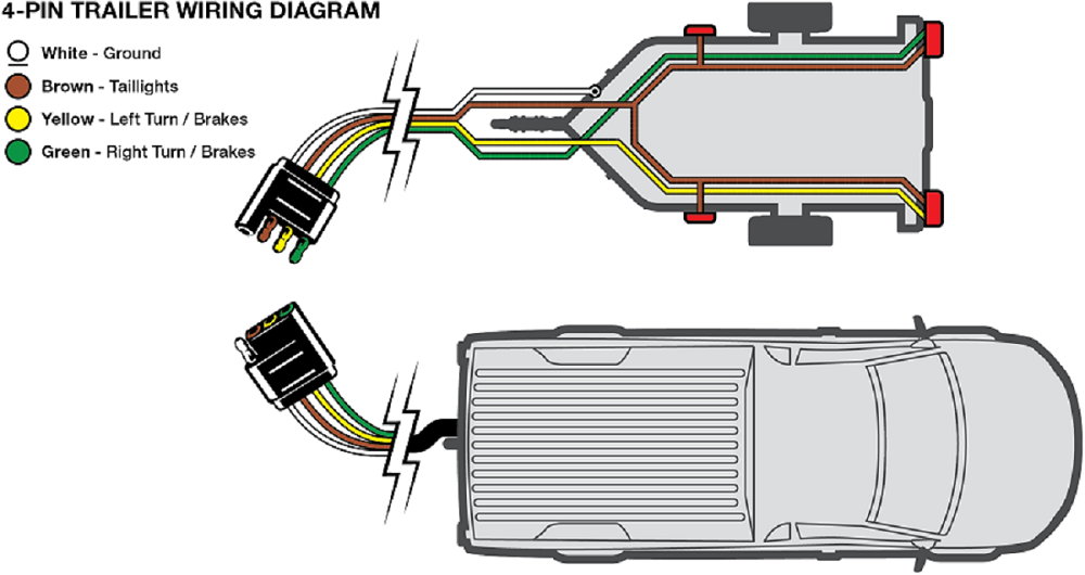
- Pin 1 (White): Ground. This is the return path for all electrical circuits. A solid, reliable ground connection is absolutely critical.
- Pin 2 (Yellow): Left Turn Signal/Brake Light. This wire carries the signal for the left turn signal and the brake light on the left side of the trailer. They are combined on this wire.
- Pin 3 (Green): Right Turn Signal/Brake Light. Similar to the yellow wire, this handles the right turn signal and brake light on the right side of the trailer.
- Pin 4 (Brown): Tail/Running Lights. This wire provides power to the trailer's tail lights (also known as running lights) that illuminate whenever your vehicle's headlights are on.
Understanding these assignments is the first step in diagnosing any lighting problems.
Symbols and Diagram Explanation
A wiring diagram uses specific symbols and conventions to represent electrical components and connections. Here's a breakdown of what you might see:
- Solid Lines: These represent wires. The thickness of the line doesn't usually indicate wire gauge on a simple diagram like this.
- Dotted Lines: Sometimes used to indicate connections within a component or optional wiring.
- Rectangles: Often used to represent the connectors themselves, with pins clearly marked.
- Circles: Typically represent light bulbs or other small electrical components.
- Ground Symbol (Looks like an upside-down tree): Indicates a connection to the vehicle's chassis, providing a ground path.
- Color Codes: As mentioned earlier, color codes are essential. The diagram will typically show "WH" for white, "YL" for yellow, "GN" for green, and "BN" or "BR" for brown.
A typical 4-pin flat trailer wiring diagram will show the vehicle-side connector and the trailer-side connector, with lines connecting the corresponding pins. The color codes will be clearly labeled on each wire. The ground wire will be shown connected to the vehicle's chassis.
How It Works
The system works by transferring electrical signals from your vehicle's lighting system to the trailer's lights through the 4-pin connector. When you activate your turn signal, the vehicle's turn signal circuit sends a signal through the corresponding wire (yellow for left, green for right) to the trailer's turn signal light. The same wire is used for the brake light signal. When you turn on your headlights, the vehicle's tail light circuit sends power through the brown wire to illuminate the trailer's tail lights. The white wire provides a consistent ground connection, ensuring a complete electrical circuit.
Crucially, the brake light and turn signal functions share a single wire on each side. This is a key difference from some other trailer wiring configurations and is essential to keep in mind when troubleshooting.
Real-World Use: Basic Troubleshooting Tips
Here are some common problems and how to troubleshoot them using your knowledge of the 4-pin flat wiring diagram:
- No Lights at All:
- Check the ground connection (white wire) first. A loose or corroded ground is the most common cause of total lighting failure. Clean the connection point on both the vehicle and the trailer frame.
- Inspect the vehicle-side connector for corrosion or damaged pins.
- Check the trailer-side connector similarly.
- Use a multimeter to test for voltage at the vehicle-side connector when the corresponding lights are activated.
- One Turn Signal Not Working:
- Check the bulb. Seems obvious, but often overlooked!
- Inspect the wiring and connector on the affected side (yellow for left, green for right). Look for breaks or corrosion.
- Use a multimeter to test for voltage at the trailer-side connector when the turn signal is activated.
- Tail Lights Not Working:
- Check the bulb.
- Inspect the brown wire and its connections.
- Test for voltage at the trailer-side connector when the vehicle's headlights are on.
- Brake Lights Not Working: Since brake lights share a wire with turn signals, if *only* the brake lights are failing, investigate the vehicle's brake light switch. It's unlikely to be the trailer wiring itself unless the turn signals also malfunction.
Safety Considerations
Working with electrical systems always involves risks. Here are some key safety precautions to keep in mind:
- Disconnect the Battery: Before working on any wiring, disconnect the negative terminal of your vehicle's battery. This prevents accidental shorts and potential electrical shocks.
- Use a Circuit Tester: A circuit tester or multimeter is essential for safely checking for voltage and continuity.
- Wear Safety Glasses: Protect your eyes from sparks or debris.
- Avoid Water: Never work on electrical systems in wet conditions.
- Proper Wire Gauges: Ensure you're using appropriately sized wiring for the load. Undersized wires can overheat and cause fires. For trailer lighting, 16-gauge or 14-gauge wire is typically sufficient.
- Careful with the 12V system Remember that even though the system runs on 12V DC, shorts can produce high amp output resulting in heat and fire.
A special note about corrosion: Trailer wiring is often exposed to the elements, making it prone to corrosion. Use dielectric grease on all connections to prevent corrosion and ensure reliable performance.
With a solid understanding of the 4-pin flat trailer wiring diagram, you're well-equipped to handle common trailer wiring issues. Remember to always prioritize safety and double-check your work. Happy towing!
To further assist you, we have prepared a detailed wiring diagram file that you can download. This diagram visually represents the connections and color codes discussed in this article, making it easier for you to understand and apply the information.