Four Wire 4 Wire Thermostat Wiring Color Code
Let's talk thermostats. Specifically, four-wire thermostats, a common setup in many modern HVAC systems. Understanding the wiring of these devices is crucial for anything from simple troubleshooting to replacing an aging unit or even upgrading your system. This guide is aimed at experienced DIYers like yourselves, providing the technical details you need without getting bogged down in unnecessary jargon. We'll cover the purpose of understanding these diagrams, key specs, how the system works, real-world troubleshooting, and safety precautions. By the end, you'll be able to confidently approach a four-wire thermostat wiring project.
Purpose of Understanding Four-Wire Thermostat Wiring
Why bother learning about thermostat wiring? There are several key reasons:
- Repair and Maintenance: Identifying a loose wire or understanding why your furnace isn't responding to the thermostat is the first step in diagnosing the problem. Without understanding the wiring, you're flying blind.
- Replacement and Upgrade: Replacing an old thermostat with a new one, especially if it's a smart thermostat with more features, requires accurately connecting the wires. A mistake here can damage the thermostat or the HVAC system.
- Troubleshooting HVAC Issues: Often, thermostat problems are related to wiring issues. A broken wire, a short circuit, or incorrect connections can all cause malfunctions. Understanding the wiring allows you to isolate the thermostat as the problem source.
- Learning and Customization: Deep diving into your home's systems provides knowledge of how your systems operate. The more you understand, the better you can adapt or upgrade things yourself.
Key Specs and Main Parts
Before we dive into the wiring itself, let's identify the key components and specifications involved.
- Thermostat: The control center of your HVAC system. It reads the room temperature and signals the heating or cooling system to turn on or off.
- HVAC System: This includes the furnace (heating), air conditioner (cooling), and any other components like heat pumps or ventilation systems.
- Wiring: The conductors that carry the low-voltage signals between the thermostat and the HVAC system. In a four-wire system, each wire has a specific purpose.
- Transformer (Typically in the HVAC Unit): The HVAC system utilizes low-voltage control signals. The transformer reduces the 120V (or 240V) line voltage to a lower voltage (usually 24VAC) used by the thermostat and HVAC control circuits.
Key Specifications:
- Voltage: Most four-wire thermostats operate on low voltage, typically 24VAC (Volts Alternating Current). This is crucial for safety.
- Wiring Gauge: Thermostat wiring is usually thin (e.g., 18 or 20 gauge) because it carries low current.
- Wire Insulation: Each wire is insulated to prevent short circuits.
- Terminal Labels: The back of the thermostat and the HVAC control board have labeled terminals (R, W, G, Y) that correspond to the different wires.
Symbols and Color Codes
Understanding the symbols and color codes is vital for interpreting any thermostat wiring diagram. These are standard across most manufacturers, but it's always a good idea to double-check.
- Lines: Represent the wires connecting the thermostat to the HVAC system. Solid lines indicate a direct connection.
- Circles/Squares: These represent terminal blocks on both the thermostat and the HVAC system.
- Letters: These are the terminal designations and are the most important part.
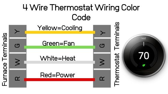
Common Color Codes and Terminal Designations:
- R (Red): Power (24VAC). This wire provides the power to the thermostat. It is sometimes labeled as Rc (Cooling Power) or Rh (Heating Power) in systems with separate transformers for heating and cooling.
- W (White): Heat. This wire activates the heating system when the thermostat calls for heat.
- G (Green): Fan. This wire controls the blower fan, allowing it to run independently of the heating or cooling.
- Y (Yellow): Cooling. This wire activates the air conditioning system when the thermostat calls for cooling.
Important Note: While these are the standard color codes, it's essential to verify the actual wiring in your system, as previous installations might deviate from the standard. Always check against the manufacturer's documentation.
How It Works
The four-wire thermostat acts as a sophisticated switch, controlling the flow of 24VAC power to different components of the HVAC system. Here's a breakdown:
- Temperature Sensing: The thermostat constantly monitors the room temperature using a thermistor or other temperature sensor.
- Set Point Comparison: The thermostat compares the measured temperature to the desired temperature (the set point) you've programmed.
- Signal Activation: If the room temperature is below the set point in heating mode, the thermostat closes a circuit, connecting the R (red) wire to the W (white) wire. This sends 24VAC to the furnace control board, signaling it to turn on the heating system. A similar process occurs for cooling, connecting R to Y.
- Fan Control: When the system is running, the furnace (or air conditioner) control board usually activates the fan automatically. However, the G (green) wire allows you to manually control the fan. When you select "Fan On" at the thermostat, it connects the R wire to the G wire, sending 24VAC to the fan relay, which turns on the blower motor.
- Power Relay Activation: The 24VAC signals from the thermostat activate relays in the HVAC equipment (furnace, AC). These relays in turn switch on the high-voltage components (blower motor, gas valve, compressor).
Essentially, the thermostat is a low-voltage control system that directs power to the appropriate components based on your desired temperature and fan settings.
Real-World Use: Basic Troubleshooting Tips
Now, let's put this knowledge into practice. Here are some common issues and how to troubleshoot them with your newfound understanding.
- No Heat or Cooling:
- Check the Thermostat Settings: Make sure the thermostat is set to the correct mode (heat or cool) and the temperature is set appropriately.
- Check the Breaker: Ensure the breaker for the HVAC system is not tripped.
- Check the Wiring: Look for loose wires or corrosion at the thermostat and the HVAC control board. Gently tug on each wire to ensure it's securely connected.
- Test the Voltage: Use a multimeter to check for 24VAC between the R wire and the W (for heat) or Y (for cooling) wire when the thermostat is calling for heat or cooling. If there's no voltage, the thermostat might be faulty or the transformer may be dead.
- Fan Not Working:
- Check the Fan Setting: Make sure the fan is set to "On" at the thermostat.
- Check the Wiring: Inspect the green (G) wire for loose connections.
- Test the Voltage: Check for 24VAC between the R wire and the G wire when the fan is turned on.
- Thermostat Display Blank:
- Check the Batteries: Many digital thermostats are battery-powered. Replace the batteries if they are low.
- Check the R Wire: Ensure the red (R) wire is securely connected, as it provides power to the thermostat.
Important Note: If you're not comfortable working with electrical components, it's always best to consult a qualified HVAC technician.
Safety Considerations
Working with electrical components always carries inherent risks. Here are some critical safety precautions to keep in mind:
- Turn Off the Power: Always turn off the power to the HVAC system at the breaker before working on any wiring. This is the most important safety precaution.
- Use a Voltage Tester: Verify that the power is off before touching any wires.
- Wear Safety Glasses: Protect your eyes from debris or sparks.
- Avoid Wet Environments: Never work on electrical components in wet or damp conditions.
- Work with a Buddy: If possible, have someone nearby who can assist you in case of an emergency.
- Transformer Hazard: The transformer in the HVAC unit converts high voltage to low voltage. Even though it's "low voltage", 24VAC can still give you a jolt. And NEVER directly work with the high-voltage side of the transformer unless you're a qualified electrician.
Disclaimer: This information is for educational purposes only and should not be considered a substitute for professional advice. Always consult with a qualified HVAC technician if you're unsure about any aspect of thermostat wiring or HVAC system repair.
We have created a downloadable wiring diagram that details the concepts described in this article. This will assist in making sure you wire your system correctly.