
Free Automotive Wiring Diagram Software
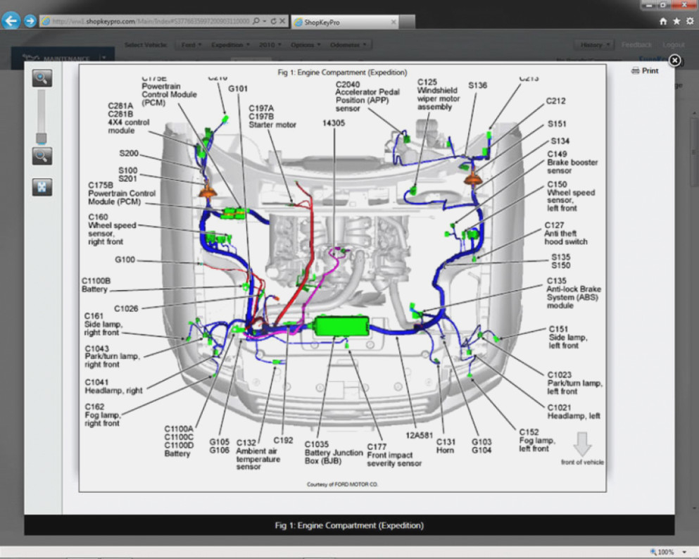
Alright, let's talk about automotive wiring diagrams. These aren't just pretty pictures – they're the lifeline when you're tackling electrical repairs, upgrades, or even just trying to understand how your car's complex systems work. Think of them as the blueprints for your car's nervous system.
Purpose of Automotive Wiring Diagrams
So, why bother with these diagrams? The main reasons are pretty straightforward:
- Troubleshooting: Imagine a flickering headlight or a malfunctioning sensor. Without a wiring diagram, you're basically poking around in the dark. A diagram allows you to trace the circuit, identify potential breaks, shorts, or faulty components, and pinpoint the problem quickly and efficiently.
- Repairing Electrical Problems: Once you've identified the source of the problem, the diagram shows you exactly how to fix it. You'll know which wires to splice, which connectors to replace, and how everything connects to each other.
- Performing Upgrades and Modifications: Planning to install a new stereo system, aftermarket lighting, or a custom alarm? A wiring diagram is essential for safely and correctly integrating these components into your car's electrical system. It helps you avoid accidentally frying something or creating a dangerous short circuit.
- Learning and Understanding: Even if you're not actively repairing anything, studying wiring diagrams is a fantastic way to learn how your car's electrical systems work. You'll gain a deeper understanding of how different components interact and how various systems are interconnected.
Key Specs and Main Parts of a Wiring Diagram
Before we dive in, let's break down the key elements you'll typically find in a wiring diagram. Understanding these basics is crucial for navigating the diagrams effectively.
Key Specs
- Voltage (V): Indicates the electrical potential difference in a circuit. Most car circuits operate at 12V (Volts).
- Current (A): Represents the flow of electrical charge, measured in Amperes (Amps). Knowing the current capacity is important for choosing the right fuse and wiring gauge.
- Resistance (Ω): Measured in Ohms, this is the opposition to the flow of electrical current. Faults can often be traced to increased resistance.
- Wire Gauge (AWG): Specifies the thickness of the wire. Thicker wires can carry more current. Using the correct gauge is essential for safety and proper operation.
Main Parts Depicted
- Power Source: This is typically the battery or the alternator. It's usually represented by a symbol indicating its voltage (e.g., 12V).
- Ground: This is the return path for the electrical current. In automotive applications, the chassis of the car usually serves as the ground. Ground points are crucial, and a bad ground can cause all sorts of problems.
- Switches: These control the flow of electricity to different components. Common types include toggle switches, rocker switches, and multi-position switches.
- Fuses and Circuit Breakers: These are safety devices that protect the circuit from overcurrents. They're designed to blow (open) the circuit if the current exceeds a certain limit, preventing damage to components and potentially preventing fires.
- Relays: These are electrically operated switches that allow a low-current circuit to control a high-current circuit. They're commonly used to control headlights, horns, and other high-power devices.
- Loads: These are the devices that consume electrical energy, such as headlights, motors, sensors, and control modules (ECUs).
- Connectors: These are the physical interfaces that connect different wires and components together. They often have specific shapes and pin configurations.
Decoding Wiring Diagram Symbols
Wiring diagrams use a standardized set of symbols to represent different components and connections. Learning these symbols is key to understanding the diagram. Let's look at some common ones:
- Lines: Lines represent wires. Solid lines typically indicate power wires, while dashed lines might indicate signal wires or ground wires. Line thickness can sometimes indicate wire gauge.
- Colors: Wires are color-coded to help identify them. Common colors include red (power), black (ground), blue, green, yellow, and white. The diagram will usually have a color code key.
- Ground Symbol: Usually represented by a series of horizontal lines getting smaller as they go down. This is a very common symbol.
- Resistor Symbol: A jagged line.
- Capacitor Symbol: Two parallel lines, often curved.
- Diode Symbol: A triangle pointing to a line. Indicates current flows in one direction only.
- ECU/Module: Often represented by a rectangular box.
Beyond these basics, there are symbols for various sensors (e.g., temperature sensors, pressure sensors), actuators (e.g., motors, solenoids), and other specialized components. It's always a good idea to refer to the diagram's legend for a complete list of symbols.
How It Works: Tracing a Circuit
Okay, let's see how to use a wiring diagram to trace a circuit. Imagine you're troubleshooting a malfunctioning windshield wiper motor. Here's the general approach:
- Identify the Wiper Motor Circuit: Find the section of the wiring diagram that shows the windshield wiper motor circuit. This usually involves looking for the wiper motor symbol and associated components.
- Trace the Power Supply: Start at the power source (usually the battery, through the ignition switch). Follow the wire from the power source to the wiper motor. Look for any switches, fuses, or relays in the circuit.
- Check for Breaks or Shorts: Use a multimeter to check for voltage at various points along the circuit. If you're not getting voltage where you expect it, there's likely a break in the wire or a blown fuse. Also, check for shorts to ground.
- Inspect the Ground Connection: Make sure the wiper motor has a good ground connection. A loose or corroded ground connection can cause all sorts of problems.
- Test the Motor Itself: If you've verified that the motor is getting power and has a good ground, the motor itself may be faulty.
This process of tracing the circuit, checking for voltage, and inspecting connections is the fundamental way to troubleshoot electrical problems using a wiring diagram.
Real-World Use: Basic Troubleshooting Tips
Here are some practical troubleshooting tips when using wiring diagrams:
- Start with the Simplest Checks: Before tearing everything apart, check the fuses first! A blown fuse is often the cause of electrical problems.
- Use a Multimeter: A multimeter is an essential tool for electrical troubleshooting. Learn how to use it to measure voltage, current, and resistance.
- Check Connections: Loose or corroded connections are a common cause of electrical problems. Clean and tighten all connections in the circuit.
- Isolate the Problem: Try to isolate the problem to a specific area of the circuit. This will make it easier to pinpoint the cause.
- Don't Guess: Use the wiring diagram to guide your troubleshooting. Don't just start randomly replacing parts.
For example, if your car's headlights don't turn on, but the parking lights do, the problem likely lies in the headlight circuit itself. Consult the wiring diagram to trace the circuit from the headlight switch to the headlights, checking for voltage and continuity along the way. Look for a common point of failure, like a relay or a shared ground.
Safety Considerations
Working with automotive electrical systems can be dangerous if you're not careful. Here are some important safety precautions:
- Disconnect the Battery: Always disconnect the negative terminal of the battery before working on any electrical circuits. This will prevent accidental shorts and shocks.
- Be Aware of High-Voltage Components: Some components, such as the ignition system, can operate at very high voltages. Avoid touching these components when the engine is running. The ignition system is extremely dangerous.
- Use Insulated Tools: Use tools with insulated handles to prevent electric shock.
- Work in a Well-Ventilated Area: Some automotive fluids, such as battery acid, can release harmful fumes. Work in a well-ventilated area to avoid breathing these fumes.
- Don't Work Alone: It's always a good idea to have someone else present when you're working on electrical systems, especially if you're not experienced.
Remember, even a 12V system can deliver a painful shock, and a short circuit can easily start a fire. Always take the necessary safety precautions.
We hope this article helps you to get started with the automotive wiring diagrams. These files are essential to diagnosing and fixing most electrical issues in vehicles.