Free Online Auto Repair Manuals Free Auto Repair Diagrams
Welcome, fellow gearheads! Finding reliable information for DIY auto repair can be a challenge. While manufacturer-specific repair manuals are the gold standard, they can be expensive. Fortunately, a wealth of free online auto repair manuals and diagrams are available, offering a powerful tool for diagnosing problems, performing maintenance, and even tackling some modifications. This article will guide you through understanding these resources, focusing specifically on electrical diagrams, which are critical for troubleshooting electrical issues. We'll demystify the symbols, explain how circuits function, and provide tips for using these diagrams effectively and safely.
Understanding Auto Repair Diagrams
Purpose
Auto repair diagrams serve several critical purposes:
- Diagnostics: Pinpointing the source of a problem, especially electrical issues, becomes far easier with a clear diagram. You can trace circuits, identify components, and test voltages or resistances at specific points.
- Repairs: Whether you're replacing a sensor, repairing a wire harness, or rebuilding an engine component, diagrams provide the necessary information to ensure you're doing it correctly.
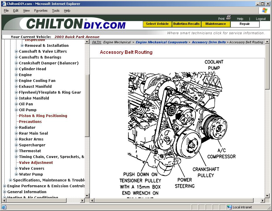
- Learning: Even if you're not actively repairing something, studying diagrams is an excellent way to understand how different systems in your car work.
- Modifications: Adding aftermarket accessories, such as lights, alarms, or performance parts, often requires tapping into existing circuits. A diagram helps you identify the correct wires and avoid damaging other components.
Key Specs and Main Parts (Focus: Electrical Diagrams)
Let's concentrate on electrical diagrams, as they can be the most confusing. A typical electrical diagram will show:
- Power Source: Usually the battery, represented by a symbol resembling two parallel lines (one longer than the other).
- Fuses and Relays: Fuses are safety devices that protect circuits from overcurrent. Relays are electromechanical switches that allow a low-current circuit to control a high-current circuit. They're vital for managing power distribution to various components.
- Switches: These control the flow of electricity to different circuits. They can be manually operated (like a headlight switch) or controlled by sensors (like a brake light switch).
- Wiring Harnesses: Bundles of wires connecting different components. The diagram will often show the wire colors and the connectors they plug into.
- Ground Points: These are connections to the vehicle's chassis, providing a return path for the current. Good grounding is crucial for proper electrical system operation.
- Sensors and Actuators: Sensors provide information to the vehicle's computer (ECU), while Actuators are devices that perform actions based on the ECU's commands. Examples include oxygen sensors, fuel injectors, and solenoids.
- ECU (Engine Control Unit) or PCM (Powertrain Control Module): The "brain" of the car, controlling various engine and transmission functions.
Symbols – Decoding the Visual Language
Understanding the symbols is key to interpreting any diagram. Here's a breakdown of common electrical diagram symbols:
- Solid Lines: Represent wires. Thicker lines generally indicate wires carrying higher current.
- Dashed Lines: May indicate shielded wires or wires that are part of a data bus (like a CAN bus). They can also mean that a connection only exists under specific conditions.
- Colors: Wire colors are typically abbreviated (e.g., "BLU" for blue, "RED" for red, "BLK" for black). These abbreviations are usually consistent across different diagrams.
- Numbers: Numbers next to wires indicate the wire gauge (thickness). Lower numbers mean thicker wires.
- Geometric Shapes: Represent different components:
- Resistors: Zigzag line.
- Capacitors: Two parallel lines of equal length.
- Inductors: Coiled line.
- Diodes: Triangle pointing to a line.
- Transistors: Three lines connected to a circle.
- Connectors: Represented by various shapes indicating the type of connector. Pay attention to the connector number, as this will help you locate the physical connector in the vehicle.
- Arrows: Indicate the direction of current flow (conventional current flow is from positive to negative).
It's essential to consult the diagram's legend, as symbols can vary slightly between manufacturers and even different models.
How It Works – Tracing the Circuit
The beauty of an electrical diagram lies in its ability to illustrate how a circuit functions. Imagine you're troubleshooting a faulty headlight. You'd start by identifying the headlight circuit in the diagram. You'll see the power source (battery), the fuse, the headlight switch, the wiring to the headlight bulb, and the ground connection.
By tracing the circuit, you can identify potential points of failure. Is the fuse blown? Is the switch working properly? Is there a break in the wiring? Is the bulb itself bad? Using a multimeter, you can test for voltage and continuity at various points in the circuit to isolate the problem.
Continuity is a complete and unbroken path for electrical current. A break in the wiring means you have no continuity.
Real-World Use – Basic Troubleshooting Tips
Here are some practical tips for using electrical diagrams for troubleshooting:
- Start with the Obvious: Check the fuse first. A blown fuse is often the simplest explanation for an electrical problem.
- Use a Multimeter: A multimeter is your best friend when troubleshooting electrical circuits. Learn how to use it to measure voltage, resistance (Ohms), and continuity.
- Follow the Circuit: Start at the power source and trace the circuit step-by-step, checking for voltage and continuity at each point.
- Isolate the Problem: Disconnect components one at a time to isolate the faulty part. For example, if you suspect a short circuit, disconnecting components can help you narrow down the location of the short.
- Check Ground Connections: Poor ground connections are a common cause of electrical problems. Make sure all ground connections are clean and secure.
- Don't Guess: Use the diagram and your multimeter to systematically diagnose the problem. Avoid replacing parts without confirming that they are actually faulty.
Safety – Respect the Electricity
Working with electrical systems can be dangerous. Here are some important safety precautions:
- Disconnect the Battery: Whenever possible, disconnect the negative battery cable before working on the electrical system. This will prevent accidental short circuits and shocks.
- Use Insulated Tools: Use tools with insulated handles to protect yourself from electric shock.
- Be Careful Around Airbags: Airbags are explosive devices that can be triggered by electrical signals. Follow the manufacturer's instructions for disabling the airbag system before working near airbags.
- Never Work Alone: It's always a good idea to have someone nearby in case of an emergency.
- High Voltage Areas: Be extremely cautious near the ignition system (spark plugs, ignition coil) as these areas carry very high voltage.
Important note: working on high-voltage components such as the high-voltage battery in hybrid or electric vehicles should only be performed by qualified and trained technicians.
By understanding auto repair diagrams, especially electrical diagrams, you can greatly enhance your ability to diagnose and repair your vehicle. These resources are invaluable for both simple maintenance tasks and complex troubleshooting procedures. Take your time, study the diagrams carefully, and always prioritize safety.
We have the electrical wiring diagram of your vehicle model. To get the electrical diagram file, please provide your vehicle model.