
Free Online Automotive Wiring Diagrams
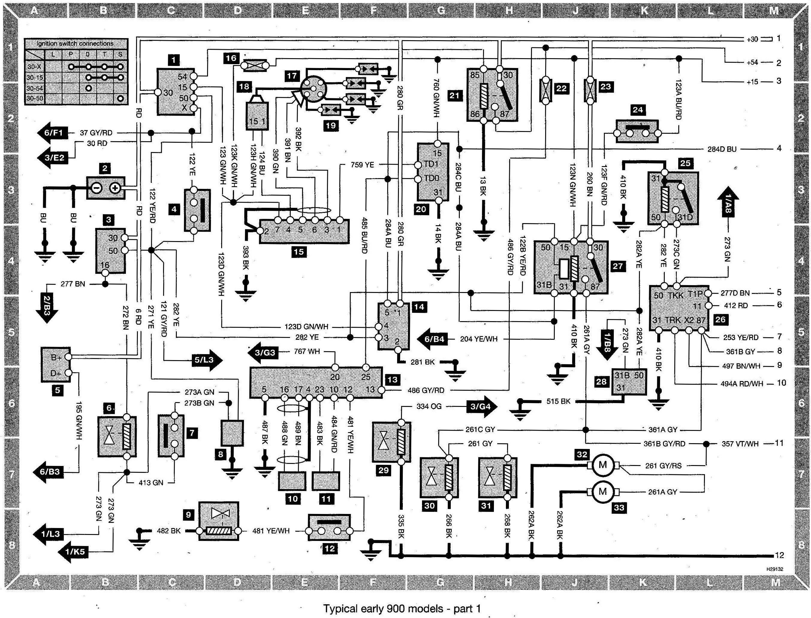
For the seasoned DIY car enthusiast, access to accurate and comprehensive automotive wiring diagrams is like possessing the Rosetta Stone for your vehicle's electrical system. Whether you're tackling a complex repair, installing aftermarket accessories, or simply deepening your understanding of how your car works, a good wiring diagram is an indispensable tool. Luckily, many resources offer free online automotive wiring diagrams, but knowing how to find them, interpret them, and use them safely is critical. Let's dive in.
Purpose: Why Wiring Diagrams are Essential
Automotive wiring diagrams serve several crucial purposes:
- Repair and Troubleshooting: Identifying faulty wiring, short circuits, open circuits, and component failures becomes infinitely easier with a clear diagram. You can trace circuits, pinpoint voltage drops, and test continuity to isolate the problem.
- Installation of Aftermarket Accessories: Adding new stereos, lights, alarms, or other electronic components requires understanding the existing wiring system. A diagram helps you tap into the correct power sources, signal lines, and ground points without damaging the factory wiring.
- Vehicle Modification and Customization: For those undertaking more extensive modifications, such as engine swaps or custom wiring harnesses, diagrams are essential for planning and executing the changes safely and effectively.
- Education and Understanding: Even if you're not currently working on your car, studying wiring diagrams can significantly improve your understanding of automotive electrical systems.
Key Specifications and Main Parts of a Wiring Diagram
A typical automotive wiring diagram represents the electrical circuits within a specific system or component of a vehicle. Understanding its key specifications and main parts is paramount.
Power Source
The power source is usually the car battery. Often it's represented by a symbol similar to a capacitor. There are always fuses protecting the circuits.
Ground
Grounds are points where the circuit is connected to the car's chassis, providing a return path for the current. The symbol for ground usually consists of one or more horizontal lines decreasing in length.
Wires and Connections
Wires are represented as solid lines, sometimes with color codes indicated. The thickness of the line does *not* necessarily indicate the wire gauge (wire thickness). Connections between wires are usually shown as dots or junctions where lines intersect. Splices can be represented by a T-shape or a dot.
Components
Components like relays, switches, sensors, actuators, and modules are represented by standardized symbols. For example, a relay coil is typically drawn as a coil of wire, while a switch is shown as a movable contact that can open or close a circuit.
Fuses and Circuit Breakers
These are safety devices that protect the circuit from overcurrent. Fuses are represented as a wavy line within a rectangle, while circuit breakers often have a similar symbol with an added toggle switch.
Abbreviations and Notes
Wiring diagrams often contain abbreviations for wire colors (e.g., BK for Black, RD for Red, BL for Blue), component names, and circuit functions. Notes may provide additional information about specific circuits or components.
Symbols: Decoding the Language of Wiring Diagrams
Understanding the symbols used in wiring diagrams is essential for accurate interpretation. Here's a breakdown of common symbols:
- Lines: Solid lines represent wires, while dashed lines might indicate shielding or grounding connections. The thickness of the lines doesn't always correlate to wire gauge.
- Colors: Wire colors are typically indicated by abbreviations (e.g., WH for White, GR for Green). Color codes help you identify specific wires within a harness.
- Icons: Standardized icons represent various electrical components:
- Resistors: Zigzag line.
- Capacitors: Two parallel lines.
- Inductors/Coils: Coiled line.
- Diodes: Triangle pointing to a line.
- Transistors: More complex symbol with base, collector, and emitter.
- Switches: Line pivoting between two points.
- Relays: Combination of coil and switch symbols.
- Ground: Series of horizontal lines decreasing in length.
- Connectors: Often represented as a square block with numbers.
How It Works: Tracing a Circuit
The fundamental principle of a wiring diagram is to visually represent the flow of electricity through a circuit. To trace a circuit, start at the power source (typically the battery), follow the wire through any switches, relays, fuses, or components, and then back to ground. Consider a basic circuit for a headlight. You would start at the battery, trace the positive (+) wire to a fuse, then to the headlight switch. When the switch is turned on, current flows through the switch to the headlight, illuminating it. From the headlight, the current returns to the battery through the ground wire connected to the car's chassis.
By following the lines and identifying the components along the way, you can understand how the circuit functions and troubleshoot any problems. Remember to pay attention to wire colors and connection points. A break in any part of the circuit will cause the component to fail.
Real-World Use: Basic Troubleshooting Tips
Wiring diagrams are invaluable for troubleshooting electrical problems. Here are some basic tips:
- Identify the Symptom: Clearly define the problem. Is a component not working? Is there a short circuit blowing fuses?
- Locate the Relevant Diagram: Find the wiring diagram for the specific system or component that's malfunctioning.
- Trace the Circuit: Follow the wiring diagram to trace the circuit from the power source to the component and back to ground.
- Check for Continuity: Use a multimeter to check for continuity (a complete electrical path) along the circuit. An open circuit indicates a broken wire or a faulty connection.
- Check for Voltage: Use a multimeter to check for voltage at various points in the circuit. No voltage indicates a problem upstream.
- Isolate the Problem: By systematically checking continuity and voltage, you can isolate the faulty component or wiring section.
For example, if your headlights are not working, you would first check the fuse. If the fuse is blown, replacing it might solve the problem, but if it blows again immediately, it indicates a short circuit. Using the wiring diagram, you can trace the headlight circuit to identify potential sources of the short, such as damaged wiring or a faulty headlight switch.
Safety: Handling Risky Components
Working with automotive electrical systems can be dangerous if proper precautions are not taken. Always disconnect the negative battery cable before working on any electrical component. Pay particular attention to these risky components:
- Airbag Systems: Airbags are triggered by electrical signals. Disconnecting the battery and waiting several minutes allows the system to discharge and prevents accidental deployment. Refer to the vehicle's service manual for specific airbag disabling procedures.
- High-Voltage Systems (Hybrid/Electric Vehicles): These vehicles contain high-voltage batteries and components that can be lethal. Only qualified technicians should work on these systems.
- Fuel Pumps: Fuel pumps operate on electrical power and can be a fire hazard if not handled properly. Disconnect the fuel pump relay or fuse before working on the fuel system.
- Capacitors: Large capacitors can store a significant electrical charge even after the battery is disconnected. Discharge capacitors before handling them.
Always use appropriate safety equipment, such as insulated tools and gloves. If you are unsure about any aspect of the electrical system, consult a qualified mechanic.
Get Your Diagram Here!
Now that you understand the importance of automotive wiring diagrams, you're probably eager to get your hands on one. We have a sample file available for download. It includes detailed schematics for [Specific System, e.g., the starting circuit of a 2010 Honda Civic]. Click the link below to download the diagram and start exploring!
Download the [Specific System] Wiring Diagram here.