Front Bumper Diagram For 2007 Mustang Gt 4.6
Alright, let's dive into the front bumper diagram for your 2007 Mustang GT 4.6. Whether you're planning a repair, prepping for a custom mod, or just want a better understanding of your Pony's anatomy, knowing your way around this diagram is invaluable. Think of it as a roadmap for the front end – it shows you how everything fits together and where potential problems might lurk.
Purpose of the Front Bumper Diagram
This diagram isn't just a pretty picture; it serves several critical purposes:
- Repair Guidance: Accident? Parking mishap? The diagram helps you identify damaged parts and order the correct replacements. No more guessing games at the auto parts store.
- Modification Planning: Thinking about adding a chin spoiler, fog lights, or a complete bumper replacement? The diagram reveals mounting points, clearances, and potential interference issues before you start wrenching.
- Troubleshooting: Got a loose bumper cover, a rattling sound, or misaligned components? The diagram helps you systematically check mounting hardware, brackets, and supports.
- General Understanding: Even if you don't plan on doing any work yourself, understanding the diagram gives you a better appreciation for how the front of your Mustang is constructed and how the various components interact.
Key Specs and Main Parts
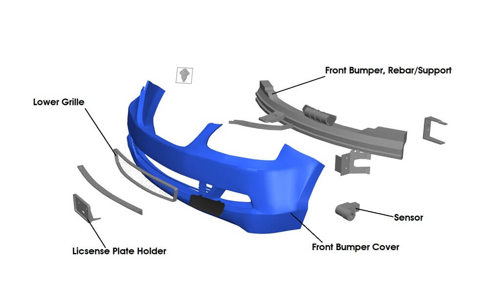
The 2007 Mustang GT front bumper is more than just a piece of plastic; it's a complex assembly of components designed for aesthetics, aerodynamics, and pedestrian safety. Here are the key parts you'll find in the diagram:
- Bumper Cover: This is the visible, painted part of the bumper. It's typically made of a flexible plastic like polyurethane (PU) or polypropylene (PP). Its primary function is to improve aerodynamics and protect underlying components from minor impacts.
- Bumper Reinforcement Bar: This is a structural steel or aluminum beam located behind the bumper cover. It's designed to absorb significant impact energy in a collision, protecting the vehicle's frame and occupants. The diagram will show its mounting points and overall shape.
- Energy Absorbers (Crush Zones): These are typically foam or honeycomb-structured components located between the bumper cover and the reinforcement bar. They're designed to collapse progressively during an impact, further dissipating energy. These are sometimes referred to as *impact absorbers*.
- Fog Lights (if equipped): The diagram will show the location of the fog lights, wiring harnesses, and mounting brackets. The wiring diagrams often link to the main front bumper diagram to illustrate how the lighting is connected.
- Grilles and Inserts: The upper and lower grilles allow airflow to the radiator and other engine components. The diagram will show how they're attached to the bumper cover.
- Mounting Brackets and Hardware: A variety of brackets, clips, screws, and bolts are used to secure the bumper assembly to the vehicle's frame. The diagram will detail the location and type of each fastener. Pay special attention to torque specifications!
- Headlight Assemblies (Indirectly): While the headlights aren't strictly part of the bumper, the diagram often shows their proximity and mounting points relative to the bumper cover.
Understanding the Diagram's Symbols
Diagrams use standardized symbols to convey information efficiently. Here's a breakdown of common symbols you'll encounter:
- Solid Lines: Indicate visible component edges or outlines. Thicker lines usually represent structural components like the reinforcement bar.
- Dashed Lines: Often indicate hidden components, like the energy absorbers behind the bumper cover. They can also represent the path of wiring harnesses.
- Arrows: Show the direction of force, the direction of movement for removal or installation, or the direction of airflow.
- Numbers and Letters: Correspond to a parts list or legend that identifies each component and its part number. Pay close attention to these!
- Torque Values: Often listed next to bolt symbols. These indicate the correct torque setting for tightening the fastener. Use a torque wrench to avoid over-tightening or under-tightening.
- Color Coding: Some diagrams use color to differentiate between materials (e.g., steel, plastic, rubber) or to highlight specific components or systems (e.g., electrical wiring).
- Component Callouts: These are lines pointing to specific components with labels describing what they are.
How It Works: Bumper Assembly Function
The front bumper assembly is designed to perform several crucial functions:
- Aesthetic Appeal: The bumper cover provides the overall look of the front end.
- Aerodynamic Efficiency: The shape of the bumper is designed to reduce drag and improve fuel economy.
- Low-Speed Impact Protection: The bumper cover and energy absorbers protect the underlying components from minor impacts, such as parking lot bumps.
- High-Speed Impact Protection: The bumper reinforcement bar and energy absorbers are designed to absorb significant impact energy in a collision, protecting the vehicle's frame and occupants. This is achieved by crumpling in a controlled manner to dissipate the kinetic energy of a crash.
- Pedestrian Safety: Modern bumper designs incorporate features to reduce the severity of injuries to pedestrians in the event of a collision.
- Component Mounting: The bumper assembly provides a secure mounting point for headlights, fog lights, grilles, and other accessories.
Real-World Use: Basic Troubleshooting Tips
Here are some common problems you might encounter with your 2007 Mustang GT front bumper and how the diagram can help you troubleshoot them:
- Loose Bumper Cover: Check the mounting brackets, clips, and screws. The diagram will show you where each fastener is located. A common culprit is broken or missing clips, easily identified on the diagram and replaced.
- Rattling Sound: Inspect the energy absorbers, grilles, and fog lights for looseness. The diagram will help you identify potential sources of vibration.
- Misaligned Bumper: Check the mounting brackets and frame for damage. The diagram will help you identify bent or broken components.
- Fog Light Malfunction: Use the wiring diagram (often linked to the bumper diagram) to trace the wiring harness and check for loose connections or damaged wires. Use a multimeter to test for voltage at the fog light connector.
- Sagging Bumper: Check the condition of the bumper reinforcement bar, and its attachment points to the frame. Corrosion can weaken these points.
Safety Considerations
Working on the front bumper can involve some risks, so take these precautions:
- Electrical Components: Disconnect the battery before working on any electrical components, such as fog lights. This prevents accidental shorts or shocks.
- Sharp Edges: Be careful of sharp edges on the bumper cover and reinforcement bar. Wear gloves to protect your hands.
- Airbag Sensors: Some vehicles have airbag sensors located in the front bumper area. Handle these sensors with extreme care! Consult the service manual for proper procedures for disconnecting and handling airbag sensors. Improper handling can cause accidental airbag deployment.
- Jacking and Support: Always use jack stands to support the vehicle when working underneath it. Never rely solely on a jack.
- Torque Specifications: Always use a torque wrench to tighten fasteners to the correct torque specification. Over-tightening can damage components, while under-tightening can lead to looseness.
Remember to consult the official service manual for your 2007 Mustang GT for the most accurate and up-to-date information. This article provides a general overview but should not be considered a substitute for professional advice or the manufacturer's instructions.
We have the detailed front bumper diagram file available for download. It's a high-resolution image that you can zoom in on and print out for use in your garage. It includes all the necessary part numbers and torque specs to get the job done right.