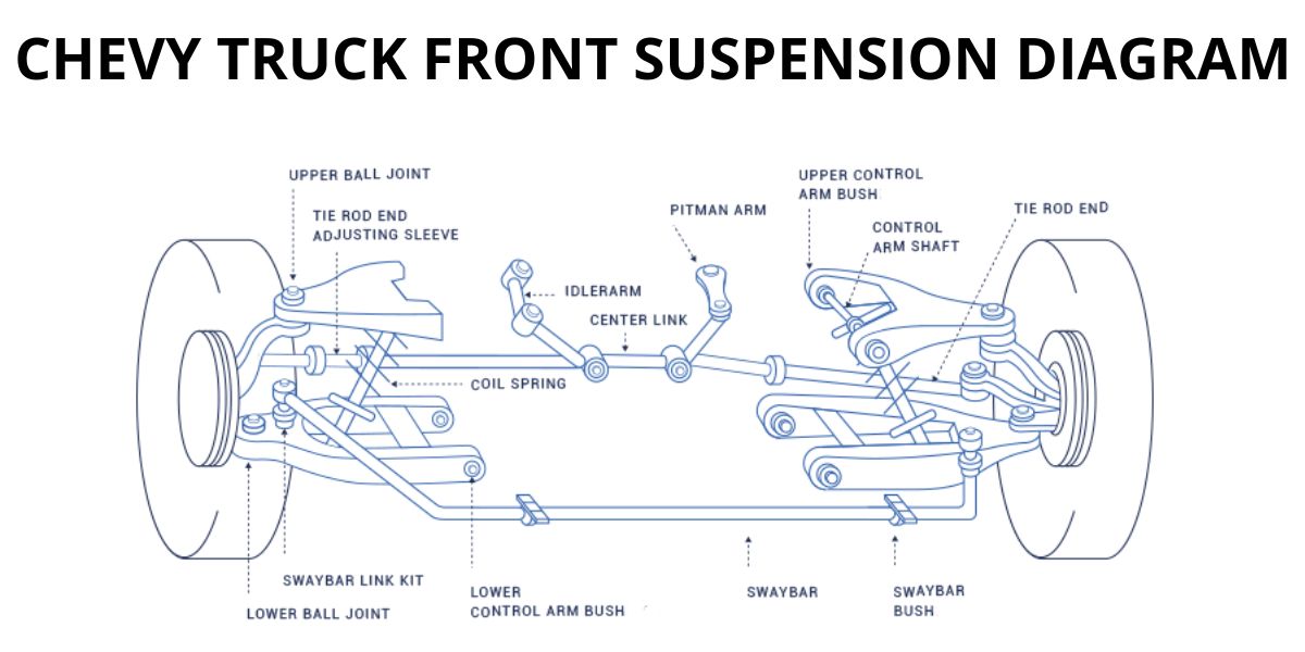
Front End Chevy Truck Front Suspension Diagram
Understanding the front suspension system in your Chevy truck is crucial for everything from routine maintenance to performance upgrades. A detailed front end suspension diagram is your roadmap to navigating this complex assembly. Whether you're diagnosing a persistent wobble, planning a lift kit installation, or simply expanding your automotive knowledge, this guide will break down the diagram and its components in a clear and accessible way.
Why You Need This Diagram
Think of the front suspension diagram as the Rosetta Stone for your truck's handling. It serves several vital purposes:
- Diagnostics: Pinpointing the source of noises, vibrations, or handling issues.
- Repair & Maintenance: Identifying specific parts needed for replacement and understanding their relationship to other components.
- Modification & Upgrades: Planning and executing modifications like lift kits, lowering springs, or performance shocks.
- Understanding System Function: Learning how each component contributes to the overall ride quality and handling characteristics.
Without a clear understanding of the suspension system, you risk misdiagnosing problems, ordering the wrong parts, or even causing further damage. The diagram provides a visual representation, making it easier to grasp the system's intricacies.
Key Specs and Main Parts
Chevy truck front suspension designs vary depending on the model year and drivetrain (2WD vs. 4WD). However, some core components are common to most models. Let's break down the essential parts, along with some typical specifications:
Common Components
- Upper and Lower Control Arms: These A-shaped or wishbone-shaped arms connect the steering knuckle (where the wheel is mounted) to the vehicle's frame. They allow vertical wheel movement while maintaining the wheel's alignment. Specs vary widely, but consider materials (forged steel, cast aluminum) and bushing types (rubber, polyurethane).
- Steering Knuckle (Upright): This component houses the wheel hub/bearing assembly and connects to the control arms and steering linkage.
- Coil Springs (or Torsion Bars in some 4WD models): These provide the primary suspension support, absorbing bumps and maintaining ride height. Spring rates (measured in lbs/inch or N/mm) determine the stiffness of the suspension.
- Shock Absorbers (Dampers): These control the rate of spring compression and rebound, preventing excessive bouncing and maintaining tire contact with the road. Shock types include hydraulic, gas-charged, and adjustable.
- Ball Joints: These spherical bearings connect the control arms to the steering knuckle, allowing for smooth articulation. They are wear items and require periodic inspection and replacement.
- Tie Rods (Inner and Outer): These connect the steering rack to the steering knuckles, transmitting steering input to the wheels.
- Sway Bar (Anti-Roll Bar): This torsion spring connects the left and right sides of the suspension, reducing body roll during cornering.
- Wheel Hub/Bearing Assembly: Allows the wheel to rotate smoothly. Sealed units are common and require replacement as a complete assembly.
- Bump Stops: These limit suspension travel, preventing damage to other components when the suspension is fully compressed.
Important Note: 4WD trucks often utilize a torsion bar suspension instead of coil springs. Torsion bars are essentially long, springy bars that are twisted to provide suspension support. Adjusting the torsion bar preload affects ride height.
Understanding Diagram Symbols
The diagram isn't just a picture; it's a technical document that uses standardized symbols. Here's a breakdown of common conventions:
- Lines: Different line weights and styles represent different types of connections and components. Solid lines usually indicate physical parts, while dashed lines might represent hidden components or vacuum lines (if applicable).
- Colors: Colors can vary depending on the diagram, but they often differentiate between different systems or materials. For example, blue might represent hydraulic fluid lines, while red could indicate electrical wiring (related to ABS sensors, if present).
- Hatching and Cross-Sections: Hatching or cross-sectional views indicate the internal structure of a component. This is helpful for understanding how parts are assembled.
- Arrows: Arrows indicate the direction of movement or force. For example, arrows might show the direction of suspension travel or the flow of hydraulic fluid within a shock absorber.
- Abbreviations: Expect to see abbreviations like "UCA" (Upper Control Arm), "LCA" (Lower Control Arm), "ABS" (Anti-lock Braking System), and "TORQUE" (followed by a value, indicating tightening specifications).
Most diagrams will include a legend or key that explains the specific symbols used. Always refer to the legend to ensure you're interpreting the diagram correctly.
How It Works: A Simplified Explanation
The front suspension is designed to isolate the vehicle's chassis from road imperfections, providing a comfortable ride and maintaining tire contact for optimal handling. Here's a simplified explanation of how it all works:
- When the wheel encounters a bump, it moves vertically.
- This vertical movement is absorbed by the coil spring (or torsion bar), which compresses.
- The shock absorber dampens the spring's oscillations, preventing the vehicle from bouncing excessively.
- The control arms allow the wheel to move vertically while maintaining its alignment.
- The ball joints allow for smooth articulation between the control arms and the steering knuckle.
- The tie rods transmit steering input from the steering system to the wheels.
- The sway bar reduces body roll during cornering by transferring force between the left and right sides of the suspension.
The geometry of the suspension (the angles and lengths of the components) plays a crucial role in handling characteristics. Changes to ride height or component placement can affect the suspension's geometry and alter its performance.
Real-World Use: Basic Troubleshooting
A suspension diagram can be invaluable when diagnosing problems. Here are a few common issues and how the diagram can help:
- Clunking Noises: The diagram can help you locate potential sources of clunking, such as worn ball joints, loose control arm bushings, or a damaged sway bar link. Check the areas around these components for wear or damage.
- Excessive Bouncing: This often indicates worn shock absorbers. The diagram will show you the location and mounting points of the shocks, allowing you to inspect them for leaks or damage.
- Uneven Tire Wear: This can be caused by misaligned suspension. The diagram shows the components that affect alignment, such as the tie rods and control arms. It can also help you identify bent or damaged parts that might be contributing to the problem.
- Steering Play: Examine the tie rod ends and steering linkage. The diagram clarifies how these connect and where play is most likely to occur.
Important: Always consult your vehicle's service manual for specific troubleshooting procedures and torque specifications.
Safety Precautions
Working on the front suspension can be dangerous due to the presence of compressed springs and the potential for uncontrolled movement. Here are some crucial safety precautions:
- Spring Compression: Never attempt to remove a coil spring without using a proper spring compressor. These tools safely compress the spring, preventing it from releasing with tremendous force. Torsion bars also store significant energy and must be handled with care.
- Jacking and Support: Always use jack stands to support the vehicle securely before working underneath it. Never rely solely on a jack.
- Wheel Chocks: Use wheel chocks to prevent the vehicle from rolling.
- Eye Protection: Wear safety glasses to protect your eyes from debris.
- Torque Specifications: Always tighten fasteners to the specified torque values. Over-tightening can damage components, while under-tightening can lead to loosening and failure.
Specifically concerning ball joints: Before separating a ball joint, understand that they can be under significant tension. Use a ball joint separator tool (pickle fork or ball joint press) and be prepared for a sudden release.
Remember, if you're unsure about any aspect of the repair, it's always best to consult a qualified mechanic. While the diagram provides a wealth of information, hands-on experience and proper safety precautions are essential for successful and safe repairs.
We have access to a comprehensive front end Chevy truck front suspension diagram that can further assist you. Please inquire and we can provide you with the file for download to aid in your repairs.