
Front End F250 Steering Parts Diagram
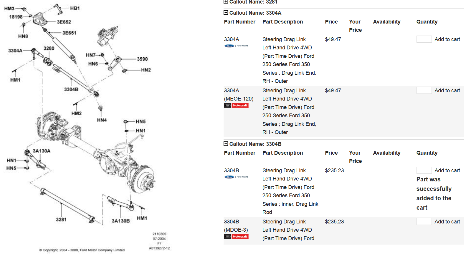
Alright, let's dive deep into the front end steering system of your Ford F250. Understanding the parts diagram isn't just about looking at pretty pictures; it's about empowering you to diagnose issues, perform repairs, and even upgrade your truck's handling with confidence. This article is designed to give you a solid understanding of the components, their function, and how it all works together. We're going to approach this like a trusted mechanic walking you through the process, focusing on clarity and practical application.
Purpose of the F250 Steering Diagram
Why bother learning about a steering diagram? Several reasons jump to mind:
- Diagnostics and Repair: The most obvious benefit. When you're experiencing steering problems – wandering, excessive play, or strange noises – the diagram helps you pinpoint the potential culprits. Knowing where each part is located is crucial for visual inspection and testing.
- Parts Identification and Ordering: Ever tried ordering a "thingamajig" for your truck and getting the wrong part? The diagram gives you the correct names and often part numbers, ensuring you get the right replacement components.
- Modification and Upgrades: Planning to install a lift kit, upgraded steering stabilizer, or different steering gear? The diagram is your roadmap, showing you how everything connects and interacts. This is invaluable for a smooth and successful installation.
- Understanding the System: Even if you don't plan on doing any repairs yourself, knowing how the steering system works gives you a better understanding of your truck and allows you to communicate more effectively with your mechanic.
Key Specs and Main Parts
The front end of an F250, especially the Super Duty models, utilizes a robust steering system. While specific designs can vary slightly depending on the year and trim level, the core components remain consistent. Here’s a breakdown of the key players:
- Steering Gearbox (or Steering Rack): The heart of the system. This component amplifies the input from the steering wheel and translates it into lateral movement to steer the front wheels. F250s typically use a recirculating ball type steering gearbox.
- Pitman Arm: Connected directly to the output shaft of the steering gearbox, the Pitman Arm converts the rotary motion from the gearbox into linear motion.
- Drag Link: This crucial link connects the Pitman Arm to the steering knuckle or tie rod assembly on one side of the vehicle. It transmits the steering force to the wheels.
- Tie Rods (Inner and Outer): Tie rods are adjustable links that connect the drag link to the steering knuckles on both sides. They are responsible for transferring the steering force from the drag link to the individual wheels, causing them to turn. Inner tie rods connect to the center link (if equipped) or directly to the steering knuckle. Outer tie rods connect to the steering knuckle.
- Steering Knuckles: These are the pivot points for the front wheels. The tie rods connect to the steering knuckles, causing them to rotate and steer the wheels.
- Steering Stabilizer (Optional): This dampening shock absorber helps to control unwanted steering vibrations and oscillations, especially important with larger tires or rough terrain.
- Idler Arm/Pitman Arm Support (on some models): Some F250 models, especially older ones, may use an idler arm instead of a drag link. The idler arm provides a pivot point on the passenger side, mirroring the Pitman arm on the driver's side, for increased stability.
- Ball Joints: Allow for vertical movement of the suspension while maintaining steering control. They connect the steering knuckle to the upper and lower control arms.
Understanding the Symbols in the Diagram
Steering diagrams use a variety of symbols to represent different components and connections. While there isn't a universal standard, here are some common conventions:
- Solid Lines: Typically represent rigid connections or solid components, like tie rods or the Pitman arm.
- Dashed Lines: May indicate a flexible connection, such as a hydraulic hose connected to the power steering pump, or a hidden component.
- Arrows: Indicate the direction of force or movement. For example, an arrow pointing along a tie rod would show the direction of steering force.
- Circles or Dots: Often represent connection points, like where a bolt connects two parts.
- Hatch Marks or Cross-Hatching: Indicate a threaded connection.
- Different Colors (in some diagrams): Colors might be used to differentiate between different systems or components. For example, hydraulic lines for power steering might be colored blue.
- Component Icons: Each part has a unique icon representing its shape. These may appear simplified but still allow you to distinguish between a tie rod, steering gearbox or stabilizer.
Always refer to the specific legend provided with your diagram for the most accurate interpretation of the symbols used.
How It Works: A Simplified Explanation
The F250 steering system is a marvel of mechanical engineering. Here’s a simplified overview of how it all comes together:
- You turn the steering wheel.
- The steering shaft transfers this rotational input to the steering gearbox.
- Inside the gearbox, a recirculating ball mechanism (or another type depending on your model) amplifies your steering input and converts it into linear motion.
- This linear motion is then transferred to the Pitman arm, which pivots in response.
- The Pitman arm pushes or pulls on the drag link.
- The drag link transfers this force to the tie rod assembly.
- The tie rods, connected to the steering knuckles, push or pull on the knuckles, causing the front wheels to turn.
Power steering, if equipped, uses a hydraulic pump to assist the gearbox, making it easier to turn the wheel, especially at low speeds. The pump provides hydraulic pressure to the gearbox, reducing the effort required from the driver.
Real-World Use: Basic Troubleshooting Tips
Now let's put this knowledge into practice. Here are some basic troubleshooting tips, using the steering diagram as your guide:
- Excessive Steering Play: Check the tie rod ends, Pitman arm, and drag link for wear and looseness. With the diagram, you can easily locate these components and visually inspect them. Also, check the steering gearbox itself for internal wear.
- Wandering or Drifting: Could be due to worn tie rod ends, loose ball joints, or a misaligned front end. Use the diagram to locate the ball joints on your steering knuckles. A visual inspection is important, but often requires a pry bar to check for play.
- Vibrations or Shaking: Could be caused by a loose steering stabilizer (if equipped), unbalanced tires, or worn suspension components. Refer to your diagram to check that the stabilizer mounting points are secure.
- Steering Wheel Hard to Turn: Check the power steering fluid level, the power steering pump belt, and the power steering pump itself. Locate these components, and follow their lines to the steering box on the diagram. This will help you visually inspect lines for wear or kinks.
Important Note: Many steering components require specialized tools for removal and installation. If you're not comfortable with these procedures, it's best to consult a qualified mechanic.
Safety: Highlighting Risky Components
The steering system is critical for your safety, so be extra cautious when working on it. Pay close attention to these areas:
- Steering Gearbox: Disconnecting the steering shaft can be tricky and requires careful attention to alignment during reinstallation. If not done correctly, it can lead to steering wheel misalignment or even damage to the airbag system (if equipped).
- Tie Rod Ends: These are crucial for maintaining wheel alignment. Incorrect installation or tightening can lead to premature wear and dangerous handling issues.
- Ball Joints: Worn or damaged ball joints can cause catastrophic failure, leading to loss of steering control. Inspect them regularly and replace them promptly if necessary.
- Power Steering System: Be careful when working with hydraulic fluid. It can be harmful if ingested or comes into contact with your skin. Depressurize the system before disconnecting any lines.
Always use proper safety precautions, including wearing safety glasses, gloves, and using jack stands when working under your vehicle.
By understanding the steering system diagram and the function of each component, you can approach repairs and upgrades with greater confidence and ensure your F250 handles safely and predictably. Remember to double-check all connections after any work is performed and consider having a professional alignment performed to ensure optimal handling and tire wear.
Now that you've learned more about your F250's steering system, you can take a look at the steering parts diagram in detail. To help with your repairs and modifications, we have the front end F250 steering parts diagram available for you to download and view.