Front Suspension 2010 Mazda 3 Seat Bolt Location Diagram
Understanding the front suspension system of your 2010 Mazda 3 is crucial for both routine maintenance and more complex repairs. A seat bolt location diagram might seem unrelated, but it’s often necessary to remove the seat to access certain suspension components or when performing extensive work in the footwell. This detailed guide will walk you through the front suspension system, explain the relevance of seat bolt locations, and provide troubleshooting tips, all while emphasizing safety.
Purpose of the Diagram
The seat bolt location diagram, in conjunction with the front suspension diagram, serves several critical purposes:
- Repair and Maintenance: Provides precise locations for removing the front seats, which can be necessary to access parts related to the suspension system like the shock tower or during wiring harness work.
- Modification: Offers a reference point for custom modifications, such as installing aftermarket seats or reinforcing the chassis near the suspension mounting points.
- Learning: Enables you to understand the structural layout of your Mazda 3, facilitating a deeper knowledge of how the suspension integrates with the vehicle's frame.
Key Specs and Main Parts of the 2010 Mazda 3 Front Suspension
The 2010 Mazda 3 utilizes a MacPherson strut front suspension, a common design praised for its balance of handling, comfort, and cost-effectiveness. Here's a breakdown of the key components:
- MacPherson Strut: This is the heart of the system. A strut combines the functions of a shock absorber and a coil spring into a single unit. It provides damping (controlling spring oscillations) and supports the vehicle's weight.
- Coil Spring: This helical spring absorbs impacts and supports the vehicle's weight, providing ride height. Its spring rate, measured in pounds per inch (lbs/in) or Newtons per millimeter (N/mm), determines how stiff the suspension feels.
- Shock Absorber (Damper): Located within the strut, the shock absorber dampens the oscillations of the coil spring, preventing the car from bouncing excessively. Hydraulic fluid passing through calibrated orifices generates resistance, converting kinetic energy into heat.
- Lower Control Arm: This arm connects the wheel hub to the vehicle's chassis. It pivots, allowing the wheel to move up and down. The ball joint, located at the outer end, allows for steering.
- Ball Joint: A spherical bearing that connects the lower control arm to the steering knuckle. It allows for both vertical and rotational movement of the wheel.
- Steering Knuckle (Upright): This component holds the wheel hub and provides a mounting point for the brake caliper. It pivots on the ball joint, allowing the wheels to steer.
- Sway Bar (Anti-Roll Bar): A torsion bar that connects the left and right sides of the suspension. It resists body roll during cornering by transferring force from one side of the suspension to the other. The sway bar end links connect the sway bar to the struts.
- Sway Bar End Links: Connect the sway bar to the strut assembly. These links transmit the twisting force of the sway bar to the suspension, helping to reduce body roll.
- Wheel Hub/Bearing Assembly: The hub is what the wheel attaches to. The bearing allows the wheel to rotate smoothly. A failing bearing will often cause a humming or grinding noise.
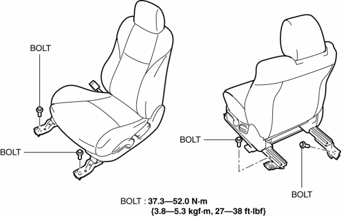
Seat Bolt Locations: The four (typically) seat bolts are usually Torx or hex-head bolts. They secure the seat frame to the floor of the vehicle. The diagram will illustrate their exact locations, often hidden beneath plastic covers.
Understanding Diagram Symbols
Automotive diagrams utilize standardized symbols for clarity. Here's a general guide:
- Solid Lines: Typically represent physical components or connections.
- Dashed Lines: Indicate hidden lines or components located behind others.
- Arrows: Show the direction of movement, force, or fluid flow.
- Numbers and Labels: Correspond to parts lists or specifications within the diagram. Pay close attention to torque specifications for bolts.
- Colors: While color coding isn't always consistent, different colors can indicate different systems or types of connections (e.g., electrical wiring).
- Torque Specifications: Crucial for safe reassembly. These are often listed in Newton-meters (Nm) or foot-pounds (ft-lbs). Always use a torque wrench to achieve the correct tightening force.
How the Front Suspension Works
The MacPherson strut suspension operates by absorbing road shocks and controlling body movement. When the wheel encounters a bump, the following occurs:
- The wheel moves upward, compressing the coil spring within the strut.
- The shock absorber dampens the spring's oscillations, preventing excessive bouncing.
- The lower control arm pivots, allowing the wheel to move vertically while maintaining its position relative to the chassis.
- The ball joint allows the steering knuckle to pivot for steering.
- The sway bar resists body roll by transferring force to the opposite wheel.
By working in concert, these components provide a comfortable ride, maintain vehicle stability, and allow for precise steering.
Real-World Use and Troubleshooting
Here are some common symptoms and potential causes in your 2010 Mazda 3's front suspension:
- Clunking Noises: Often caused by worn ball joints, sway bar end links, or strut mounts.
- Squeaking Noises: Can indicate dry or worn ball joints or bushings in the control arms.
- Bouncing: Worn shock absorbers are the most likely culprit. A “bounce test” (pushing down on each corner of the car) can reveal weak dampers.
- Uneven Tire Wear: Misalignment, worn ball joints, or bent suspension components can cause uneven tire wear.
- Vibration: Can be caused by unbalanced tires, bent rims, or worn wheel bearings.
- Pulling to One Side: Indicates misalignment or a problem with the braking system (caliper sticking).
Troubleshooting Tip: Before replacing any parts, visually inspect the suspension components for damage, wear, and looseness. Use a pry bar to check for play in the ball joints and bushings. Listen carefully for noises during a test drive.
Safety Considerations
Working on the front suspension can be dangerous due to the high spring forces involved. Here are some critical safety precautions:
- Always Use Jack Stands: Never work under a vehicle supported only by a jack.
- Spring Compressors: If you need to disassemble the strut, use a quality spring compressor to safely release the spring tension. Improper use of spring compressors can result in serious injury or death.
- Torque Wrench: Always use a torque wrench to tighten bolts to the manufacturer's specifications. Over-tightening can damage components, while under-tightening can lead to failure.
- Wheel Chocks: Use wheel chocks to prevent the vehicle from rolling.
- Wear Safety Glasses: Protect your eyes from flying debris.
- Battery Disconnect: Disconnect the negative battery cable before working on any electrical components, especially if dealing with ABS sensors.
The compressed spring is the single most dangerous component. If you are uncomfortable using a spring compressor, take the struts to a professional mechanic for disassembly and reassembly.
Seat Bolt Access and Considerations
While seemingly simple, removing the front seats requires care:
- Disconnect Battery (again!): Modern cars often have seat-mounted airbags or seatbelt pretensioners. Disconnecting the battery helps prevent accidental deployment.
- Locate Bolts: Use the diagram to precisely locate the seat bolts. They may be concealed under plastic trim pieces that need to be carefully pried off.
- Use the Correct Tool: Ensure you have the correct size Torx or hex socket for the bolts. Stripping the bolt head is a common issue.
- Disconnect Wiring: Carefully disconnect any electrical connectors under the seat before fully removing it. These connect to airbags, seat heaters, or seatbelt sensors. Document the connector locations for reassembly.
- Protect the Interior: Use blankets or towels to protect the interior trim from scratches during seat removal and installation.
- Torque Correctly: Upon reinstallation, torque the seat bolts to the manufacturer's specified torque. This is crucial for seat retention in the event of a collision.
By understanding the front suspension system and the role of the seat bolt locations, you can confidently tackle a wider range of maintenance and repair tasks on your 2010 Mazda 3. Remember to always prioritize safety and consult the factory service manual for specific procedures and torque specifications.
We have the front suspension and seat bolt location diagram file available for download. This diagram contains precise measurements, torque specifications, and component breakdowns to assist you in your repairs.