Front Suspension Control Arm Diagram
Alright, let's dive into the often-overlooked but crucial world of front suspension control arms. If you're wrenching on your car, especially when dealing with suspension work, understanding the control arm system is absolutely vital. This article will break down the anatomy of a typical front suspension control arm diagram, empowering you to better understand repairs, upgrades, and general maintenance. Plus, we've got a downloadable diagram you can reference as you go!
Why Understanding a Front Suspension Control Arm Diagram Matters
Why bother learning about these diagrams? The short answer: they're the roadmap to your car's handling and ride comfort. Here's a more detailed breakdown:
- Repairs and Maintenance: Diagnosing issues like clunking noises, uneven tire wear, or poor handling starts with visually inspecting the suspension. The diagram helps you identify parts that might be worn, damaged, or out of alignment. Replacing bushings, ball joints, or even the entire control arm becomes much easier with a clear understanding of the system.
- Upgrades and Modifications: Thinking about lowering your car, improving handling, or increasing wheel travel? Knowing the control arm geometry and how it interacts with other suspension components is essential for choosing the right aftermarket parts and ensuring proper installation.
- Troubleshooting: Suspension problems can be tricky. A diagram helps you trace the problem to its source. Is the ball joint binding? Are the bushings cracked? Is the control arm bent from an impact? The diagram is your visual guide.
- Learning and Understanding: Even if you're not planning on tackling a major suspension overhaul yourself, understanding how the control arm system works will make you a more informed car owner. You'll be able to better communicate with your mechanic and understand their recommendations.
Key Specs and Main Parts of a Control Arm
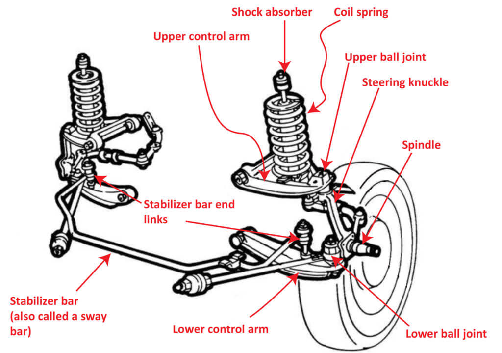
Before we dissect the diagram, let's identify the core components and some common specifications. A typical front suspension control arm system includes the following:
- Control Arm (Upper and/or Lower): The main structural component. Often made of stamped steel, forged steel, or aluminum. Their primary function is to connect the wheel hub assembly to the vehicle's frame or subframe, while allowing vertical wheel movement for suspension articulation. Some vehicles utilize an "A-arm" design, which is a single, wide control arm, while others may use separate upper and lower control arms.
- Bushings: These are flexible rubber or polyurethane pieces that isolate the control arm from the frame and dampen vibrations. They allow the control arm to pivot while minimizing noise and harshness. Common failure point.
- Ball Joint: A spherical bearing that allows the wheel hub to pivot for steering. Connects the control arm to the steering knuckle. Critical for safe steering. There are upper and lower ball joints in systems with upper and lower control arms.
- Ball Joint Boot: A rubber or plastic cover that protects the ball joint from dirt and debris. A torn boot is a sign of impending ball joint failure.
- Sway Bar Link (End Link): Connects the sway bar to the control arm or strut assembly. Helps reduce body roll during cornering.
- Mounting Points: Where the control arm bolts to the frame/subframe and steering knuckle.
Key Specs to Consider:
- Control Arm Material: Affects strength, weight, and cost.
- Bushing Material: Determines ride comfort and durability (rubber vs. polyurethane).
- Ball Joint Type: Some ball joints are replaceable, while others are integrated into the control arm.
- Control Arm Length: Affects suspension geometry and wheel travel. This is critical for lift kits and lowering kits.
- Mounting Bolt Torque Specs: Crucial for safe and reliable operation.
Understanding Symbols in a Front Suspension Diagram
Deciphering the diagram involves understanding the symbols used to represent different components and connections. While specific conventions may vary slightly between manufacturers, here are some common interpretations:
- Solid Lines: Typically represent physical components like the control arm itself, the frame, and the steering knuckle. Thicker lines often indicate heavier components.
- Dashed Lines: Might indicate hidden lines, components that are partially obscured, or the range of motion of a particular part.
- Circles or Ellipses: Often represent bushings or bearings. The center of the circle might indicate the pivot point.
- Triangles: Can indicate mounting points or specific features on a component.
- Arrows: Indicate the direction of movement or force. For example, an arrow pointing toward a bushing might indicate the direction of compression under load.
- Torque Specifications: Indicated by numbers followed by a unit of measurement (e.g., Nm or lb-ft) next to a bolt or fastener.
- Color Coding: Some diagrams use color coding to differentiate between different types of materials (e.g., steel, aluminum, rubber) or components (e.g., upper vs. lower control arms).
Note: Always refer to the specific legend or key provided with the diagram to ensure you're interpreting the symbols correctly.
How the Control Arm System Works
The control arm system is a crucial part of your car's suspension. It works in concert with the springs and shocks (or struts) to provide a smooth and controlled ride. Here's a simplified explanation:
- Vertical Wheel Movement: As the wheel encounters bumps and dips in the road, it moves vertically.
- Control Arm Pivot: The control arm pivots on its bushings, allowing the wheel to move up and down while maintaining its position relative to the frame.
- Spring and Damper Action: The spring absorbs the impact energy, while the damper (shock or strut) controls the spring's oscillation, preventing excessive bouncing.
- Ball Joint Steering: The ball joint allows the steering knuckle to pivot, enabling the driver to steer the vehicle.
- Sway Bar Influence: The sway bar, connected to the control arms via end links, helps to distribute the load during cornering, reducing body roll and improving stability.
The geometry of the control arm system (length, angle, and mounting points) is carefully designed to optimize handling, ride comfort, and tire wear. Altering the control arm geometry, either through modifications or damage, can significantly affect these characteristics.
Real-World Use: Basic Troubleshooting Tips
Here are some basic troubleshooting tips using your newfound knowledge of the control arm system:
- Clunking Noise: Often indicates worn bushings, a loose ball joint, or a broken sway bar link. Visually inspect these components for cracks, tears, or excessive play.
- Uneven Tire Wear: Can be caused by misaligned suspension. Check the control arm bushings and ball joints for wear or damage. A bent control arm will drastically affect alignment.
- Poor Handling: Could be due to worn shocks, springs, or control arm bushings. Also check the ball joints for play.
- Visual Inspection: Regularly inspect the control arms for signs of damage, such as bending, cracking, or corrosion. Pay close attention to the bushings and ball joints.
If you suspect a problem with your control arm system, it's always best to consult a qualified mechanic. However, understanding the diagram will help you communicate effectively and understand the recommended repairs.
Safety Considerations
Working on suspension components can be dangerous due to the high forces involved. Here are some critical safety precautions:
- Spring Compression: Never attempt to disassemble a strut assembly without using a proper spring compressor. The spring is under tremendous pressure and can cause serious injury if it's released unexpectedly.
- Vehicle Support: Always use jack stands to support the vehicle when working underneath it. Never rely solely on a jack.
- Torque Specifications: Always use a torque wrench to tighten fasteners to the manufacturer's specified torque. Over-tightening can damage the components, while under-tightening can lead to failure.
- Ball Joint Separator: Use a proper ball joint separator tool to safely disconnect ball joints. Using a hammer can damage the ball joint and surrounding components.
- Rust Penetrant: Generously apply rust penetrant to any corroded bolts and nuts before attempting to remove them. Stripped or broken fasteners can make the job much more difficult and dangerous.
- Wear Safety Glasses: Always wear safety glasses to protect your eyes from debris.
Disclaimer: Suspension work should only be performed by qualified individuals with the proper tools and knowledge. Incorrect repairs can lead to serious accidents.
We hope this article has provided you with a solid understanding of front suspension control arm diagrams and the overall system. Remember, this is a complex area, and further research and professional guidance may be necessary for specific repairs or modifications.
Now that you have a better understanding of the control arm and its diagram, you can download our detailed diagram file. It is a valuable resource for your future repairs, maintenance, and modification of your car's front suspension.