Front Suspension Dodge Ram 2500 Front End Diagram
So, you're diving into the front suspension of your Dodge Ram 2500? Excellent choice. Whether you're tackling a repair, planning an upgrade, or just trying to understand how your truck handles, a good front end diagram is absolutely essential. This article breaks down the diagram, covering everything from the core components to troubleshooting common issues. We'll equip you with the knowledge to confidently approach your Ram's front end. And the best part? We've got the diagram file ready for you to download. Let's get started!
Purpose of a Front End Diagram
Why is a front end diagram so important? Think of it as the blueprint for your truck's front suspension. It serves several crucial purposes:
- Repair and Maintenance: Identifying parts quickly, understanding their relationships, and ensuring proper reassembly after repairs. Without it, you're essentially working blind.
- Troubleshooting: Diagnosing issues by visualizing the entire system and pinpointing potential problem areas. A diagram helps you trace the chain of cause and effect.
- Modification and Upgrades: Planning and executing upgrades like lift kits, new shocks, or control arms requires a clear understanding of the existing system. A diagram shows you what needs to be changed and how those changes will affect other components.
- Learning: Simply understanding how your vehicle works can be incredibly satisfying. The diagram is a gateway to deeper knowledge of automotive engineering.
Key Specs and Main Parts of the Dodge Ram 2500 Front Suspension
The Dodge Ram 2500 typically employs a solid axle front suspension, known for its strength and durability – essential for heavy-duty applications. Here's a breakdown of the key components, with typical specs where applicable:
- Solid Front Axle: This is the backbone of the system, connecting the front wheels. It's a rigid beam that transmits power and supports the weight of the vehicle.
- Coil Springs: These provide the primary suspension, absorbing bumps and maintaining ride height. Spring rates (measured in lbs/in or N/mm) vary depending on the year and trim level. Heavier duty trucks will have higher spring rates.
- Shock Absorbers: Also known as dampers, these control the movement of the springs, preventing excessive bouncing and improving handling. Aftermarket options offer adjustable damping for customized performance.
- Control Arms: These arms (usually upper and lower) connect the axle to the frame. They allow the axle to move up and down while maintaining proper alignment. The Dodge Ram 2500 typically uses radius arms in conjunction with coil springs on the front axle.
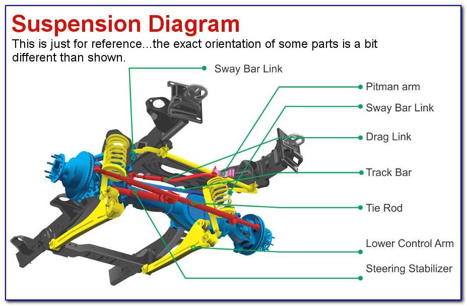
- Track Bar (Panhard Rod): This bar prevents lateral (side-to-side) movement of the axle. It's mounted to the frame on one end and the axle on the other. Its length and mounting points are critical for proper axle centering.
- Steering Linkage: This system transmits steering input from the steering wheel to the front wheels. Key components include the steering box (or rack-and-pinion on some models), pitman arm, drag link, and tie rod ends.
- Sway Bar (Stabilizer Bar): This bar reduces body roll during cornering. It connects to both sides of the suspension and resists twisting forces.
- U-Bolts: Secure the axle to the leaf springs (if equipped; some models use coil springs with radius arms). Ensuring proper torque on U-bolts is crucial for safety.
- Ball Joints: Allow for pivoting movement between the control arms and the steering knuckles. These are wear items and should be inspected regularly.
- Steering Knuckles (Spindles): Connect the wheel hub and bearing assembly to the suspension. They also provide a mounting point for the brakes.
Understanding Diagram Symbols
A front end diagram isn't just a pretty picture; it's a technical drawing with specific symbols. Here's a breakdown of common conventions:
- Lines:
- Solid Lines: Represent physical components and their connections.
- Dashed Lines: Often indicate hidden lines or components behind others.
- Thick Lines: May represent heavier components or lines that carry significant force.
- Colors: While not standardized, colors can be used to differentiate systems (e.g., steering in blue, suspension in green). Refer to the diagram's key for specific color meanings.
- Icons:
- Fasteners (Bolts, Nuts, Washers): Depicted with standard engineering symbols. Torque specifications are often listed near the fastener icons.
- Springs: Shown as coiled lines with arrows indicating the direction of force.
- Dampers (Shock Absorbers): Represented as cylinders with a piston rod.
- Lubrication Points: Highlighted with a grease zerk icon.
- Abbreviations: Common abbreviations include:
- RH: Right Hand (passenger side)
- LH: Left Hand (driver side)
- Torque (Tq): Tightening specification for fasteners.
How It Works: The Dynamics of the Front Suspension
The front suspension's primary job is to isolate the vehicle's chassis from road irregularities, providing a comfortable ride and maintaining tire contact with the road. Here's a simplified explanation:
- Impact: When a wheel encounters a bump, the impact force is transmitted to the coil spring (or leaf spring).
- Compression: The spring compresses, absorbing the energy of the impact. The amount of compression depends on the severity of the bump and the spring rate.
- Damping: The shock absorber (damper) restricts the spring's movement, preventing it from oscillating excessively. This controlled damping improves ride quality and handling.
- Axle Articulation: The control arms and track bar allow the axle to move up and down while maintaining proper alignment and preventing excessive lateral movement.
- Steering: Steering input is transmitted through the steering linkage, turning the wheels and allowing the driver to control the vehicle's direction.
- Sway Control: The sway bar resists body roll during cornering, improving stability and handling.
Real-World Use: Basic Troubleshooting Tips
A front end diagram can be your best friend when diagnosing suspension problems. Here are a few common issues and how the diagram can help:
- Excessive Bouncing: Likely a problem with the shock absorbers. The diagram helps you locate and inspect the shocks for leaks or damage.
- Clunking Noises: Could be worn ball joints, tie rod ends, or loose control arm bushings. The diagram shows the location of these components for easy inspection.
- Uneven Tire Wear: Often indicates alignment issues, worn ball joints, or bent suspension components. The diagram helps you visualize the alignment angles and identify potential problem areas.
- Wandering Steering: Could be caused by worn tie rod ends, a loose track bar, or a failing steering box. The diagram helps you trace the steering linkage and identify potential sources of play.
- Sagging Suspension: Indicates worn or damaged springs. The diagram allows you to identify the spring type and locate its mounting points for inspection.
Important: Always consult a repair manual for specific troubleshooting procedures and torque specifications.
Safety: Risky Components
Working on the front suspension can be dangerous if you're not careful. Here are some key safety considerations:
- Springs: Coil springs store a tremendous amount of energy and can be extremely dangerous if compressed improperly. Always use a proper spring compressor and follow the manufacturer's instructions carefully. Never attempt to compress a spring without the correct tools.
- Jacking and Support: Always use a sturdy jack and jack stands to support the vehicle. Never work under a vehicle supported only by a jack.
- Wheel Alignment: After any suspension work, it's essential to have the vehicle's alignment checked by a qualified technician. Improper alignment can lead to tire wear, handling problems, and safety issues.
- Brake Lines: Be extremely careful when working near brake lines. Damage to a brake line can result in brake failure.
- Torque Specifications: Always tighten fasteners to the correct torque specifications. Over-tightening can damage components, while under-tightening can lead to loosening and failure.
Remember, when in doubt, consult a qualified mechanic. Your safety is paramount.
Ready to get your hands on the Dodge Ram 2500 Front End Diagram? We have the file ready for you to download. Good luck with your project!