
Front Suspension Sway Bar Link Diagram
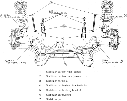
So, you're tackling a front suspension project and need to understand your sway bar link system? Excellent. Whether you're diagnosing a clunking noise, replacing worn parts, or even upgrading your suspension, a clear understanding of the sway bar link setup is crucial. This article breaks down the sway bar link diagram, covering its purpose, components, functionality, and troubleshooting, all with the goal of empowering you to confidently tackle this aspect of automotive maintenance.
Why a Sway Bar Link Diagram Matters
Why bother with a diagram in the first place? Simply put, a sway bar link diagram offers a visual representation of the entire system, highlighting the connections between the sway bar (also called an anti-roll bar), the suspension components (usually the strut or lower control arm), and the vehicle's chassis. This visualization is invaluable for:
- Diagnosis: Quickly identifying which component might be responsible for noises, play, or other issues.
- Repair: Ensuring correct part placement and torque specifications during replacement.
- Modification: Understanding how changes to one part affect the entire system. Want to install stiffer sway bars? The diagram helps visualize the impact on the links.
- Learning: Gaining a deeper understanding of vehicle dynamics and suspension geometry.
Without a clear diagram, you risk incorrect installation, potential damage to parts, or even a dangerous handling condition. Think of it as a roadmap for your suspension system.
Key Specs and Main Parts
Let's dive into the components you'll typically find in a front sway bar link system and their associated specifications. Keep in mind that designs can vary slightly between vehicle makes and models, so always refer to the specific diagram for *your* vehicle.
Main Parts:
- Sway Bar (Anti-Roll Bar): A torsion spring that connects the left and right sides of the suspension. Its job is to resist body roll during cornering. Usually a stiff steel bar.
- Sway Bar Links (End Links): These connect the sway bar to the suspension components. They transfer the force from the suspension to the sway bar and vice versa. Often these are the most common failure point.
- Sway Bar Bushings: Rubber or polyurethane bushings that mount the sway bar to the vehicle's frame or subframe. These allow the sway bar to twist and move freely while still being securely mounted.
- Mounting Brackets: Metal brackets that hold the sway bar bushings in place.
- Fasteners (Nuts & Bolts): Used to secure all the components together. Torque specifications are critical!
Key Specs:
- Sway Bar Diameter: Measured in millimeters (mm), a larger diameter generally means a stiffer bar and greater resistance to body roll.
- Link Length: The distance between the mounting points on the sway bar and the suspension component. Adjustable links are available for fine-tuning suspension geometry, especially with lowered vehicles.
- Bushing Material: Rubber offers good noise, vibration, and harshness (NVH) damping, while polyurethane provides greater stiffness and durability but can transmit more vibrations.
- Torque Specifications: The specific torque values for all fasteners. Always use a torque wrench and adhere to the manufacturer's specifications. Over-tightening can damage components, while under-tightening can lead to loosening and failure.
Deciphering the Diagram: Lines, Colors, and Icons
Understanding the symbology used in the diagram is crucial. While standards exist, always refer to the legend or key provided with the specific diagram you're using.
- Solid Lines: Typically represent physical connections or components. A thicker line might indicate a more substantial part.
- Dashed Lines: Often denote hidden components or lines that are behind other parts.
- Arrows: Indicate the direction of force or movement.
- Circles or Dots: Represent fasteners (bolts, nuts, etc.).
- Shaded Areas: Might indicate rubber or flexible components like bushings.
- Colors: Some diagrams use color coding to distinguish different materials or components. The legend will explain the color scheme.
In addition to lines and colors, diagrams often use icons to represent specific parts. For example, a small coil spring might represent a spring, or a bolt head symbol will represent where the bolt is.
How It Works: The Sway Bar System in Action
Now, let's understand how the sway bar system functions.
When a vehicle corners, the body tends to roll outwards due to centrifugal force. This roll causes the suspension on the outside of the turn to compress, while the suspension on the inside of the turn extends. The sway bar resists this difference in suspension travel.
Here's the sequence:
- Body roll initiates the difference in suspension travel.
- The sway bar links transfer this vertical motion to the sway bar.
- The sway bar twists, acting as a torsion spring.
- This twisting force is then transferred back to the opposite side of the suspension through the other sway bar link.
- The force opposes the body roll, helping to keep the vehicle flatter and more stable during cornering.
The stiffness of the sway bar determines how much it resists body roll. A stiffer bar will result in less body roll but can also lead to a harsher ride on uneven surfaces, as it transfers more movement between the left and right wheels.
Real-World Use: Basic Troubleshooting Tips
Knowing how the system works allows for effective troubleshooting. Here are some common issues and how the diagram can help:
- Clunking Noises: Often caused by worn sway bar link bushings or loose fasteners. The diagram helps you pinpoint the exact location of the noise and identify the affected component. Check for play in the link connections.
- Rattling: Similar to clunking, rattling can also be caused by loose sway bar links or worn bushings. Inspect the bushings for cracks, deformation, or excessive wear.
- Excessive Body Roll: Could indicate a broken sway bar link, damaged sway bar, or worn sway bar bushings. Use the diagram to inspect each component for damage or wear. A broken link is usually visually obvious.
- Handling Issues: Changes in handling, such as increased understeer or oversteer, could be related to a problem with the sway bar system, especially after modifications. Ensure that all components are properly installed and functioning correctly.
When diagnosing, always check the fasteners first. Many issues arise from improperly torqued bolts.
Safety: Highlight Risky Components
Working on suspension components can be dangerous, as they are under significant stress. Always take the following precautions:
- Support the Vehicle Properly: Use jack stands on a level surface to support the vehicle before working on the suspension. Never rely solely on a jack.
- Release Tension: Before disconnecting any sway bar links, ensure that the suspension is unloaded. This may involve lifting both sides of the vehicle simultaneously or using a spring compressor if necessary.
- Wear Safety Glasses: Protect your eyes from flying debris.
- Use Proper Tools: Using the correct tools, such as a torque wrench, is crucial for safe and effective repairs.
- Be Aware of Spring Compression: While the sway bar system itself doesn't store the same level of energy as a coil spring, removing links can change the forces acting on other suspension parts. Be mindful of how things might move.
The most dangerous part of suspension work is related to coil springs and struts. However, a failed sway bar link can cause a sudden loss of control, so proper installation and maintenance are essential.
With this comprehensive guide, you should have a solid understanding of sway bar link diagrams and how they apply to real-world automotive scenarios. Remember to always consult the specific diagram for your vehicle and follow all safety precautions.
To further assist you in your project, we have the diagram file available for download. This will allow you to have a detailed visual aid as you work on your vehicle's suspension system.