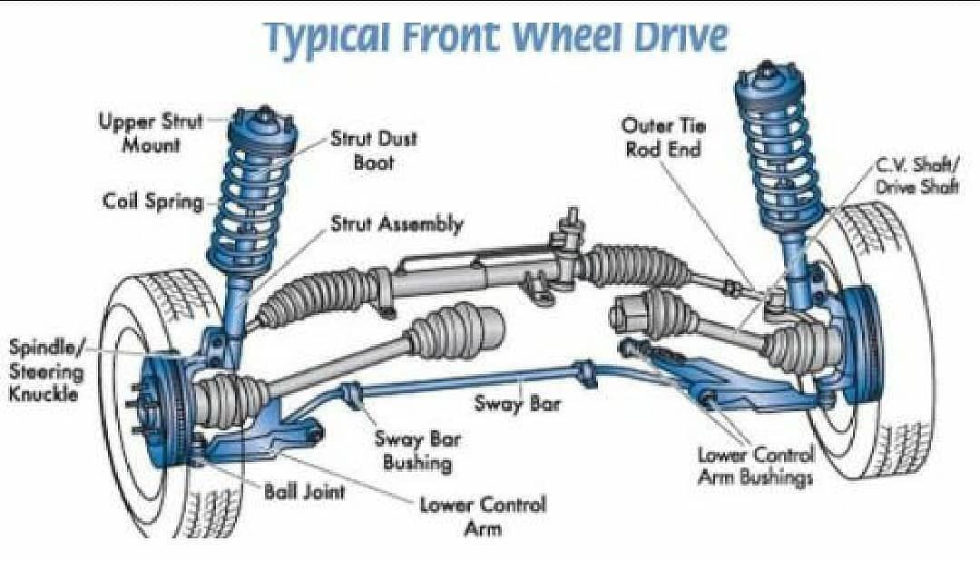
Front Wheel Drive Suspension Diagram
Alright, let's dive into the world of front-wheel drive (FWD) suspension. Understanding the diagram of a FWD suspension system is crucial whether you're planning on tackling a repair, modifying your ride for better handling, or simply expanding your automotive knowledge. We're talking about the foundation of how your car rides and handles, so understanding it gives you a serious edge.
Purpose of the FWD Suspension Diagram
Think of a suspension diagram as the roadmap for your car's front-end handling. It's more than just a pretty picture. Primarily, it serves these key purposes:
- Repair Guidance: It pinpoints the location of each component, assisting with disassembly, inspection, and reassembly during repairs. Need to replace a ball joint? The diagram shows you exactly where it is and how it connects.
- Troubleshooting Aid: It helps you understand how different parts work together to identify the source of a problem. For example, if you're experiencing excessive body roll, the diagram can guide you to inspect the sway bar and its end links.
- Modification Planning: Want to lower your car or upgrade to performance shocks? The diagram helps you understand the geometry changes that will occur and how they'll affect handling.
- Educational Tool: Simply put, it helps you learn! Understanding the layout allows you to trace the flow of forces from the road to the chassis, giving you a much deeper appreciation for automotive engineering.
Key Specs and Main Parts of a FWD Suspension
FWD suspensions are generally simpler than their rear-wheel drive counterparts, but they still involve several critical components. Here's a rundown:
Key Specs to Consider:
- Ride Height: The distance between the wheel center and the fender arch. Affects handling, appearance, and ground clearance.
- Wheel Alignment Angles: These include camber (tire tilt), caster (steering axis angle), and toe (wheel direction). Crucial for tire wear and straight-line stability.
- Spring Rate: Measured in lbs/inch (or N/mm), this defines how much force is required to compress the spring a certain distance. Higher rates mean stiffer suspensions.
- Damping Rate: Controlled by the shock absorber, it dictates how quickly the suspension settles after a bump. Affects ride comfort and handling response.
Main Parts:
- Strut Assembly: A combined unit consisting of a shock absorber (also called a damper) and a coil spring. It dampens vibrations and supports the vehicle's weight. MacPherson struts are commonly used.
- Lower Control Arm (LCA): A pivoting arm that connects the wheel hub to the vehicle's frame. It controls the wheel's vertical movement.
- Ball Joints: Spherical bearings that allow the suspension components to move up and down and turn left and right. They connect the control arm to the steering knuckle.
- Steering Knuckle/Hub: Holds the wheel bearing and provides a mounting point for the wheel and brake components. It also connects to the tie rod for steering input.
- Tie Rods (Inner and Outer): Connect the steering rack to the steering knuckle, transmitting steering forces to the wheels. Adjustable for wheel alignment (toe).
- Sway Bar (Anti-Roll Bar): A torsion bar that connects the left and right sides of the suspension. It reduces body roll during cornering by transferring forces between the wheels.
- Sway Bar End Links: Connect the sway bar to the strut or lower control arm. They transmit the twisting force of the sway bar.
- Wheel Bearings: Allow the wheels to rotate freely on the hub.
Understanding Diagram Symbols
Diagrams use symbols to represent components and connections. Here's a general guide:
- Solid Lines: Indicate physical connections between parts. Thicker lines might represent structural components.
- Dashed Lines: Often show hidden components or alternative configurations.
- Arrows: Indicate direction of movement or force transmission. For example, an arrow might show the direction of spring compression.
- Circles/Dots: Represent joints or pivot points (like ball joints).
- Color Coding: Not always present, but if used, different colors could highlight specific systems (e.g., steering system in blue, braking in red).
- Abbreviations: Common abbreviations include LCA (Lower Control Arm), UCA (Upper Control Arm - less common in FWD), and ABS (Anti-lock Braking System).
- Torque Specifications: Diagrams often include torque specs (e.g., "45 Nm") for critical bolts and fasteners. Adhering to these specs is vital for safety.
How It Works: FWD Suspension in Action
The core principle is to provide a comfortable ride while maintaining good handling. Here's a simplified explanation:
- As the wheel encounters a bump, the suspension compresses. The spring absorbs the energy of the impact.
- The shock absorber (damper) controls the spring's oscillations, preventing the car from bouncing excessively. It converts kinetic energy into heat.
- The lower control arm pivots, allowing the wheel to move vertically while maintaining its position relative to the chassis.
- The ball joints allow for the necessary articulation as the suspension moves and the steering is applied.
- The sway bar minimizes body roll during cornering. When one wheel travels upwards, the sway bar twists and transfers some of that force to the opposite wheel, helping to keep the car flatter.
- The tie rods, connected to the steering rack, translate the driver's steering input into wheel movement, enabling the car to turn.
Real-World Use: Basic Troubleshooting Tips
Here are some common FWD suspension issues and how a diagram can help with troubleshooting:
- Clunking Noises: Could be worn-out ball joints, sway bar end links, or loose strut mounts. The diagram helps you locate these components for inspection.
- Excessive Bouncing: Indicates worn-out shock absorbers. The diagram confirms the shock absorber's location within the strut assembly.
- Poor Handling/Wandering: Could be due to worn tie rod ends, ball joints, or misaligned wheels. The diagram shows you the steering linkage and alignment points.
- Uneven Tire Wear: Often a sign of misalignment (camber, caster, or toe). The diagram helps you visualize the alignment angles and how they're adjusted.
Always start with a visual inspection. Look for damaged, worn, or loose components. Then, use the diagram to understand how the suspect part interacts with the rest of the suspension system.
Safety Considerations
Working on suspension systems can be dangerous. Here's what you need to keep in mind:
- Spring Compression: Coil springs store tremendous energy. Never attempt to disassemble a strut assembly without a proper spring compressor. Improper use can lead to serious injury or death.
- Vehicle Support: Always use jack stands to support the vehicle before working underneath it. Never rely solely on a jack.
- Torque Specifications: Use a torque wrench and tighten fasteners to the specified torque values. Overtightening can damage components, while undertightening can lead to failure.
- Brake Lines: Be careful not to damage brake lines when working on the suspension. Damaged brake lines can lead to brake failure.
This explanation should give you a solid understanding of FWD suspension diagrams and how they can be useful. Remember safety first! Having the right tools and knowledge will make the process much smoother.
We have a detailed, downloadable FWD suspension diagram available. It includes precise measurements, torque specs, and expanded parts list for most common vehicles. Contact us to download the file and take your understanding of the front suspension to a new level!