Fuel Injection Fuel Injector Wiring Diagram
Understanding your fuel injector wiring diagram is crucial for a variety of tasks, from basic troubleshooting to advanced modifications. It's the roadmap to your fuel system's electrical heart, allowing you to diagnose problems, perform repairs, and even upgrade your injectors with confidence. This article will guide you through the intricacies of a typical fuel injector wiring diagram, equipping you with the knowledge to navigate this essential resource.
Purpose and Importance
Why bother understanding this diagram? Several compelling reasons exist:
- Troubleshooting: When your engine sputters, misfires, or refuses to start, the fuel injectors are often suspects. The wiring diagram lets you trace the electrical path, identifying breaks, shorts, or faulty connections.
- Repair and Replacement: Replacing a damaged injector or repairing a broken wire requires a clear understanding of the circuit. The diagram ensures you connect everything correctly.
- Performance Upgrades: Swapping out stock injectors for high-performance units demands proper wiring integration. The diagram becomes your guide for a seamless transition, especially if you're dealing with different injector impedances or connector types.
- Learning and Understanding: Delving into the wiring diagram provides a deeper understanding of how your engine management system functions. It's an excellent way to improve your automotive knowledge.
Key Specs and Main Parts
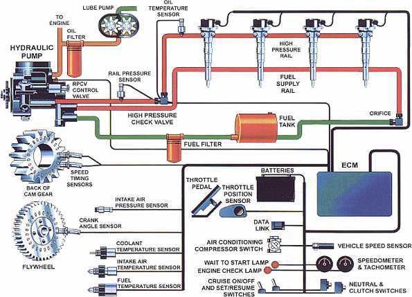
A fuel injector wiring diagram, at its core, illustrates the electrical connections between the engine control unit (ECU), the fuel injectors, and other related components. Let's break down the key components and specifications:
- ECU (Engine Control Unit): The "brain" of the operation, the ECU controls when and how long the fuel injectors are energized. It sends electrical pulses to the injectors, triggering them to spray fuel into the intake manifold.
- Fuel Injectors: These electromechanical devices precisely meter and spray fuel into the engine. Each injector typically has two wires: a power wire (often shared) and a ground/control wire managed by the ECU.
- Wiring Harness: The network of wires that connects all the components. The diagram will show the specific wire colors and gauges used in the harness.
- Connectors: These allow for easy disconnection and reconnection of components. Common connector types include EV1, EV6, and newer multi-pin connectors.
- Relays: Used to control high-current circuits, such as the fuel pump relay, which is often closely tied to the injector circuit.
- Fuses: Protect the circuit from overcurrent situations. The diagram will indicate the fuse location and amperage rating for the fuel injector circuit.
- Resistors (if applicable): Some older or low-impedance injectors require ballast resistors to limit current and prevent damage to the ECU.
Key specifications to look for include:
- Voltage: Typically 12V DC.
- Injector Resistance/Impedance: This is crucial when replacing injectors. High-impedance injectors (typically 12-16 ohms) are common and can usually be directly swapped. Low-impedance injectors (typically 2-3 ohms) require resistors.
- Wire Gauge: The thickness of the wires. Using the correct gauge is essential for safe and reliable operation.
- Connector Type: Matching the connector type ensures proper electrical connection.
Understanding the Symbols
Decoding the symbols on the wiring diagram is key to understanding the circuit. Here's a breakdown of common symbols:
- Solid Lines: Represent wires. The thickness of the line doesn't necessarily indicate wire gauge.
- Dashed Lines: Often indicate shielded wires or ground connections.
- Color Codes: Wires are typically identified by color codes (e.g., "BLU/RED" for a blue wire with a red stripe). A legend on the diagram will explain the color codes used.
- Ground Symbol: Usually a series of downward-pointing lines, indicating a connection to the vehicle's chassis ground.
- Injector Symbol: Usually a rectangle or oval with the letter "I" or "INJ" inside.
- ECU Symbol: A rectangle or square, often labeled "ECU" or "PCM" (Powertrain Control Module).
- Fuse Symbol: A zig-zag line within a rectangle. The amperage rating is often indicated nearby.
- Relay Symbol: A coil and a switch, representing the relay's components.
Important Tip: Always refer to the specific legend on your wiring diagram, as symbols can vary slightly between manufacturers.
How It Works: The Fuel Injection Sequence
Here's a simplified explanation of how the fuel injector circuit works:
- The ignition is switched on, energizing the fuel pump relay (often controlled by the ECU). This provides power to the fuel pump, which builds fuel pressure in the fuel rail.
- The ECU receives signals from various sensors (e.g., crankshaft position sensor, mass airflow sensor, throttle position sensor).
- Based on these sensor readings, the ECU calculates the required amount of fuel.
- The ECU grounds (or, in some cases, applies a voltage to) the control wire of the fuel injector. This completes the circuit, energizing the injector's solenoid.
- The energized solenoid lifts the injector needle, allowing fuel to spray into the intake manifold.
- The ECU stops grounding the control wire, de-energizing the injector and closing the needle.
- This cycle repeats rapidly, precisely controlling the amount of fuel injected into the engine.
Many modern systems use sequential fuel injection, where each injector is fired independently and precisely timed to coincide with the intake stroke of its corresponding cylinder. Older systems may use batch-fire injection, where injectors are fired in groups.
Real-World Use: Basic Troubleshooting
Let's say your engine is running rough, and you suspect a fuel injector problem. Here's how the wiring diagram can help:
- Locate the fuel injector circuit on the diagram. Identify the ECU, injectors, wiring, fuses, and relays.
- Check the fuse. Use a multimeter to verify continuity across the fuse. If it's blown, replace it with the correct amperage fuse.
- Inspect the wiring and connectors. Look for signs of damage, corrosion, or loose connections.
- Test for voltage at the injector connector. With the ignition on, use a multimeter to check for 12V at the power wire of the injector.
- Check for continuity to ground. With the engine off, use a multimeter to check for continuity between the injector control wire and ground (with the ECU disconnected to prevent damage).
- Use a noid light. A noid light plugs into the injector connector and flashes when the ECU is sending a pulse. This confirms that the ECU is signaling the injector.
- Check injector resistance. Use a multimeter to measure the resistance of each injector. Compare the readings to the manufacturer's specifications. Significant deviations may indicate a faulty injector.
Important Tip: When troubleshooting, always start with the simplest checks first (e.g., fuse, wiring, connectors) before moving on to more complex tests.
Safety Considerations
Working with automotive electrical systems can be dangerous. Keep these safety precautions in mind:
- Disconnect the battery: Always disconnect the negative battery terminal before working on the electrical system to prevent short circuits and electrical shocks.
- Work in a well-ventilated area: Fuel vapors are flammable and can be harmful to your health.
- Use appropriate tools: Use insulated tools to prevent electrical shocks.
- Be careful around fuel: Avoid spilling fuel and clean up any spills immediately.
- High-Voltage components: While the injector circuit is 12V, be aware of other high-voltage components in the engine bay, such as the ignition system.
Important Note: The ECU is a sensitive electronic device. Avoid static electricity and take precautions to prevent damage when working around it. Disconnecting the ECU while the ignition is on can cause serious damage.
Understanding and utilizing your fuel injector wiring diagram is a powerful skill that empowers you to diagnose, repair, and even upgrade your fuel system with greater confidence. Remember to consult your vehicle's specific service manual for accurate diagrams and procedures.