
Fuel Injector Wiring Harness Replacement
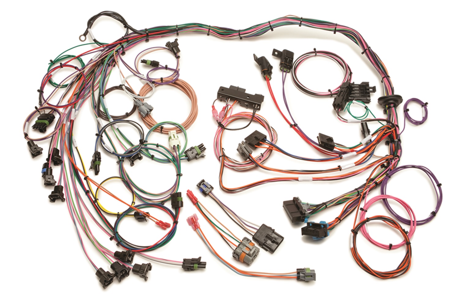
So, your engine's been acting up, maybe misfiring or running rough, and you suspect the fuel injectors. That's a solid place to start. Replacing the fuel injector wiring harness might be necessary if you've got damaged wires, corroded connectors, or persistent injector issues even after cleaning or replacing the injectors themselves. This article will give you a technical deep dive into fuel injector wiring harness diagrams, enabling you to confidently diagnose problems, perform repairs, or even undertake performance modifications.
Purpose of Understanding Fuel Injector Wiring Diagrams
Understanding a fuel injector wiring diagram isn't just about blindly following wires. It's about empowering yourself to:
- Troubleshoot injector problems effectively: Knowing the circuit allows you to pinpoint shorts, opens, or high resistance that are causing your problems.
- Perform accurate repairs: Replacing damaged connectors, wires, or even entire sections of the harness becomes much easier and safer.
- Understand engine management: The fuel injector circuit is a key component of the engine control system. Comprehending its operation gives you a broader understanding of how your engine works.
- Plan performance modifications: When upgrading injectors for more power, you need to understand how the wiring needs to be modified to accommodate the new injectors.
- Avoid costly mistakes: Incorrect wiring can damage the engine control unit (ECU) or other components. A diagram helps you get it right the first time.
Key Specs and Main Parts of a Fuel Injector Wiring Harness
Before diving into the diagram, let's define the key components and specifications you'll encounter:
- ECU (Engine Control Unit): The brains of the operation. The ECU controls when and how long each injector is activated.
- Fuel Injectors: These electromechanical devices spray a precise amount of fuel into the engine's intake manifold or directly into the combustion chamber (in direct injection systems).
- Wiring Harness: The bundle of wires connecting the ECU to the injectors and other sensors. It provides the electrical pathway for signals and power.
- Connectors: These allow for easy connection and disconnection of the injectors to the harness. They're often prone to corrosion, so inspection is crucial. There are various types of connectors, but the most common types are EV1, EV6, and Nippon Denso.
- Relays: Some systems use a fuel injector relay to provide power to the injectors. This relay is controlled by the ECU.
- Fuses: Protect the circuit from overloads. A blown fuse is often the first sign of a wiring problem.
- Ground Points: Essential for completing the circuit. Poor ground connections can cause all sorts of weird issues.
- Injector Resistance (Ohms): Fuel injectors come in two main varieties: high-impedance (typically 12-16 ohms) and low-impedance (typically 2-3 ohms). The ECU is designed to work with a specific type, and using the wrong type can damage the ECU or injectors. This is particularly important when upgrading injectors.
- Pulse Width (Milliseconds): The duration that the injector is open, controlled by the ECU. A wider pulse width means more fuel is injected.
Decoding Fuel Injector Wiring Diagram Symbols
Wiring diagrams use standardized symbols. Here's a breakdown of the key ones:
- Solid Lines: Represent wires. Thicker lines often indicate power wires.
- Dashed Lines: Can represent shielding, ground connections, or communication lines.
- Color Codes: Each wire has a color, often abbreviated (e.g., BLU for blue, RED for red, GRN for green, BLK for black, YEL for yellow). This is critical for identifying wires correctly.
- Injector Symbol: Often a rectangle or oval with a squiggle inside, representing the injector coil.
- Ground Symbol: Usually a series of descending lines, indicating a connection to the vehicle's chassis ground.
- ECU Symbol: A rectangle or square, often labeled "ECU" or "PCM" (Powertrain Control Module).
- Fuse Symbol: A squiggly line inside a rectangle or circle.
- Relay Symbol: A coil and a switch, representing the relay's operation.
- Connectors Symbol: Shown as two interlocking shapes where wires meet and connect.
How Fuel Injector Wiring Works
The typical fuel injector circuit works like this:
- Power Source: A power source, usually the car's battery, supplies voltage (typically 12V) to the fuel injector circuit. This power may go through a relay and a fuse for protection.
- ECU Control: The ECU controls the injectors by switching the ground (or sometimes the power) to the injector coil. When the ECU wants to inject fuel, it completes the circuit, allowing current to flow through the injector coil.
- Injector Activation: When current flows through the injector coil, it creates a magnetic field that pulls the injector pintle (a small valve) open. This allows fuel to be sprayed into the engine.
- Pulse Width Modulation: The ECU controls the duration of the injector opening (the pulse width). A longer pulse width means more fuel is injected. The ECU constantly adjusts the pulse width based on various sensor inputs (e.g., engine temperature, throttle position, oxygen sensor readings) to maintain the correct air-fuel ratio.
- Injector Closing: When the ECU stops grounding the injector, the magnetic field collapses, and a spring forces the pintle closed, stopping fuel flow.
It's important to remember that most modern ECUs use sequential fuel injection, where each injector is fired independently and timed to coincide with the intake stroke of the corresponding cylinder. Older systems sometimes used batch fire injection, where injectors were fired in groups, or throttle body injection (TBI), where a single or dual injector system sprays fuel into the throttle body.
Real-World Use: Basic Troubleshooting Tips
Here are some troubleshooting tips using your understanding of the wiring diagram:
- No Injector Pulse: Use a multimeter or test light to check for voltage at the injector connector with the ignition on. If there's no voltage, check the fuse and the fuel injector relay. If those are good, trace the power wire back to the ECU to check for breaks or shorts. You can also use a noid light. Noid lights plug directly into the fuel injector connector. If the ECM is commanding the injector to fire, the light will blink when the engine is cranking.
- Injector Always On: This could be a short to ground in the wiring harness, a faulty injector, or a problem with the ECU. Disconnect the injector connector. If the injector stops spraying, the problem is likely in the wiring or the injector itself. If it continues to spray, the ECU might be faulty.
- High Resistance: Use a multimeter to measure the resistance of the injector coil. Compare the reading to the specification for your injectors. High resistance indicates a problem within the injector or wiring.
- Poor Running/Misfires: Could indicate a clogged injector or a wiring issue. Check the wiring for corrosion, loose connections, or damage. Inspect the connectors carefully.
Note: Before suspecting the wiring, always rule out basic issues like a clogged fuel filter, low fuel pressure, or faulty sensors.
Safety: Handling Risky Components
Working on fuel injector wiring involves potentially hazardous components:
- Fuel System: Always relieve fuel pressure before disconnecting fuel lines or injectors. Fuel is flammable and can be dangerous.
- Electrical System: Disconnect the negative battery cable before working on any electrical components. This prevents accidental shorts and potential damage to the ECU.
- ECU: Handle the ECU with care. It's a sensitive electronic device that can be easily damaged by static electricity. Ground yourself before touching the ECU.
Remember, electricity and fuel are a dangerous combination. Take your time, be careful, and double-check your work.
We have a downloadable fuel injector wiring diagram file available. This diagram is a great resource to visually understand what has been detailed within this article.