
Fuel Rail Pressure Sensor Wiring Diagram
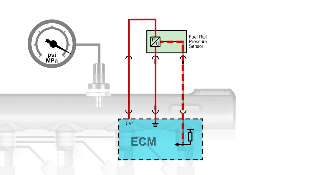
Understanding the fuel rail pressure (FRP) sensor wiring diagram is crucial for anyone serious about diagnosing and repairing modern engine management systems. Whether you're troubleshooting a performance issue, upgrading your fuel system, or simply trying to learn more about your car's inner workings, this diagram provides the roadmap you need to navigate the sensor's electrical connections and how it communicates critical data to the engine control unit (ECU).
Why This Diagram Matters
Think of the FRP sensor as the messenger, constantly relaying information about fuel pressure to the ECU. The ECU then uses this information to adjust fuel injector pulse width, ensuring the engine receives the correct amount of fuel for optimal performance and efficiency. When this messenger's connection is compromised – a broken wire, a short circuit, or a corroded connector – the entire system can be thrown into disarray. A faulty sensor or wiring issue can trigger a cascade of problems, including:
- Poor fuel economy
- Rough idling
- Hesitation during acceleration
- Stalling
- Check Engine Light (CEL) activation with related diagnostic trouble codes (DTCs)
Having access to and understanding the FRP sensor wiring diagram allows you to:
- Accurately diagnose electrical faults: Pinpoint the exact location of a break or short in the wiring.
- Perform component testing: Verify the sensor's integrity and the continuity of the wiring.
- Safely modify your fuel system: Ensure proper sensor integration during upgrades like installing a larger fuel pump or aftermarket injectors.
- Prevent misdiagnosis: Avoid replacing perfectly good parts by accurately identifying the root cause of the problem.
Key Specs and Main Parts
Let's break down the typical components and specifications you'll encounter in an FRP sensor circuit:
Main Parts:
- Fuel Rail Pressure (FRP) Sensor: The sensor itself, usually a 3-wire or 4-wire sensor, mounted directly on the fuel rail. It uses a piezoresistive or strain gauge element to measure fuel pressure and converts it into an electrical signal.
- Engine Control Unit (ECU): The "brain" of the engine management system. It receives the signal from the FRP sensor and uses it to control fuel injection.
- Wiring Harness: The network of wires connecting the sensor to the ECU and other components.
- Connectors: The electrical connectors that plug into the sensor and the ECU.
- Fuses: Protective devices that interrupt the circuit if there's an overcurrent condition, preventing damage to components.
- Relays (less common, but possible): Used to switch power to the sensor or related components.
Typical Specifications:
- Voltage Supply: Typically 5 volts DC, provided by the ECU to power the sensor.
- Signal Voltage: The voltage output from the sensor, which varies proportionally with fuel pressure. This is often between 0.5 volts (low pressure) and 4.5 volts (high pressure). The specific range depends on the sensor's calibration.
- Ground: Provides a return path for the electrical current.
- Resistance: The resistance of the sensor itself can be measured to check its internal integrity. Specific resistance values will vary based on the sensor's manufacturer and model.
Understanding Wiring Diagram Symbols
Wiring diagrams use a standardized set of symbols to represent electrical components and connections. Here's a breakdown of common symbols you'll encounter:
- Solid Lines: Represent wires. The thickness of the line doesn't usually indicate wire gauge, but rather clarity of the diagram.
- Dashed Lines: Can represent shielded wires or connections that are not always present, depending on the vehicle configuration.
- Circles: Represent connectors. Sometimes they will have numbers inside, indicating pin numbers.
- Squares: Represent components like sensors, relays, and fuses.
- Rectangles with angled lines: Represent resistors.
- Ground Symbol (often looking like an inverted pyramid): Indicates a connection to the vehicle's chassis ground.
- Battery Symbol: Indicates the vehicle's battery.
- Fuse Symbol: A wavy line or a rectangle with a line through it represents a fuse.
Wire Colors:
Wire colors are crucial for identifying specific wires in the harness. Standard abbreviations are used, such as:
- BK: Black
- RD: Red
- BL: Blue
- GN: Green
- YE: Yellow
- WH: White
- OR: Orange
- BR: Brown
Often, wires are striped, with a primary color and a secondary color. For example, "GN/WH" would indicate a green wire with a white stripe. Always consult the specific wiring diagram for your vehicle's make, model, and year, as color codes can vary.
How It Works
The FRP sensor operates on a simple principle: it converts mechanical fuel pressure into an electrical signal that the ECU can understand. Here's a simplified explanation of the circuit:
- The ECU provides a regulated 5-volt reference voltage to the FRP sensor (often labeled VREF or REF).
- The sensor's internal circuitry, which includes a piezoresistive element, changes its resistance based on the fuel pressure acting upon it.
- This change in resistance alters the voltage drop across the sensor, creating a signal voltage that varies proportionally with fuel pressure.
- The ECU reads this signal voltage and interprets it as a specific fuel pressure value.
- Based on this fuel pressure reading, along with other sensor inputs (e.g., engine speed, throttle position), the ECU adjusts the fuel injector pulse width to control the amount of fuel injected into the engine.
The wiring diagram illustrates the complete circuit, showing how the sensor is connected to the ECU's power supply, ground, and signal input pins.
Real-World Use: Basic Troubleshooting Tips
Here are some basic troubleshooting steps you can take using the FRP sensor wiring diagram:
- Visual Inspection: Check the sensor connector for damage, corrosion, or loose wires. Inspect the wiring harness for any signs of cuts, abrasions, or melted insulation.
- Voltage Testing: Use a multimeter to verify that the sensor is receiving the correct 5-volt reference voltage from the ECU. Check for a good ground connection at the sensor.
- Signal Voltage Measurement: With the engine running, measure the signal voltage at the sensor. The voltage should change proportionally with engine load and fuel demand. A static voltage or a voltage outside the expected range indicates a potential problem with the sensor or the wiring.
- Continuity Testing: With the ignition off and the sensor disconnected, use a multimeter to check the continuity of the wires between the sensor connector and the ECU connector. This will identify any breaks in the wiring.
- Resistance Testing: Check the resistance of the sensor itself using a multimeter. Compare the reading to the manufacturer's specifications.
Example: Let's say you're getting a P0191 code (Fuel Rail Pressure Sensor Circuit Range/Performance). First, visually inspect the sensor and its wiring. Then, use the wiring diagram to locate the 5V reference wire. Use a multimeter to confirm you are getting 5V at the sensor connector (with the key on, engine off). If you're not getting 5V, the problem is likely upstream – a faulty ECU or a break in the reference voltage wire. If you have 5V, move on to checking the signal wire.
Safety Precautions
Working with electrical systems always carries some risk. Keep these safety precautions in mind:
- Disconnect the Battery: Always disconnect the negative battery terminal before working on any electrical components. This will prevent accidental shorts and potential electrocution.
- Work in a Well-Ventilated Area: Gasoline fumes are flammable and can be harmful to your health.
- Use Proper Tools: Use a quality multimeter and other appropriate tools for electrical testing.
- Be Careful Around the Fuel Rail: The fuel rail is under high pressure. Do not disconnect any fuel lines without depressurizing the system first. Refer to your vehicle's service manual for the proper procedure. Improperly handling the fuel rail can result in serious injury.
- Never work on the fuel system with the engine running or the ignition on.
By carefully following these precautions and consulting the FRP sensor wiring diagram, you can safely and effectively diagnose and repair fuel system issues on your vehicle. Remember to always consult your vehicle's specific service manual for detailed instructions and specifications.
We have a comprehensive FRP sensor wiring diagram available for download, specifically tailored for [Common Vehicle Make, e.g., Ford Mustang] models between [Year Range, e.g., 2015-2020]. This diagram includes detailed pinouts, wire colors, and ECU connector locations to aid in your troubleshooting efforts. Contact us for access.