
Fuel Shut Off Solenoid Wiring Diagram
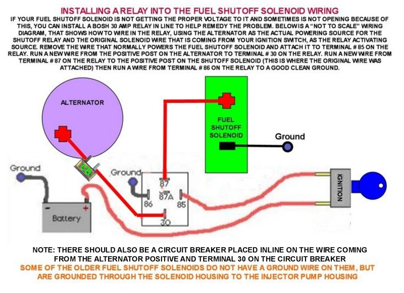
Understanding the fuel shut off solenoid wiring diagram is crucial for anyone tackling fuel system repairs, engine swaps, or even just routine maintenance on older diesel engines. This diagram provides a roadmap to the electrical components that control fuel flow, allowing you to diagnose issues, perform repairs, and even upgrade your fuel system with confidence. We're going to break down the typical diagram, explain what each component does, and give you the knowledge to interpret it effectively.
Purpose of the Wiring Diagram
Why bother with a fuel shut off solenoid wiring diagram? Several reasons. Firstly, it's indispensable for troubleshooting fuel-related problems. If your engine isn't starting, stalling unexpectedly, or experiencing fuel starvation, the diagram helps you isolate the source of the issue, be it a faulty solenoid, a broken wire, or a problem with the control circuit. Secondly, the diagram is invaluable when making modifications or upgrades. Installing an aftermarket fuel pump or a different type of solenoid requires understanding the existing wiring to ensure proper integration. Finally, having the diagram on hand provides a deeper understanding of your vehicle's systems, empowering you to perform your own repairs and maintenance, saving you time and money.
Key Specs and Main Parts
Before diving into the diagram itself, let's identify the key components and their specifications. The fuel shut off solenoid is the central element. It's an electromagnetically operated valve that controls the flow of fuel to the engine. Typically, when energized, the solenoid opens, allowing fuel to pass. When de-energized, it closes, shutting off the fuel supply. The most common type is 12V DC, but some applications use 24V DC. Its resistance is a critical parameter. A typical resistance value is between 20 to 50 ohms. A significantly lower or higher resistance than this range suggests a short or open circuit, respectively.
Here are the main parts that are usually shown on the wiring diagram:
- Fuel Shut Off Solenoid: The core component that controls fuel flow.
- Ignition Switch: Provides the power source when the key is in the "on" or "run" position.
- Fuse: Protects the circuit from overcurrent. A blown fuse indicates a potential short circuit.
- Relay (Optional): In some systems, a relay is used to switch the high current required by the solenoid, isolating the ignition switch from the direct load.
- Engine Control Unit (ECU) or Timer (Optional): Some modern engines use the ECU to control the fuel shut off solenoid based on various parameters like engine speed and temperature. Older diesel engines may use a timer that controls the solenoid for a few seconds upon starting.
- Ground Connection: Provides the return path for the electrical current. A good ground connection is essential for proper operation.
- Wiring Harness: Connects all the components together.
Symbols: Interpreting the Language of the Diagram
A wiring diagram is a symbolic representation of an electrical circuit. Understanding the symbols is paramount to interpreting the diagram accurately.
- Solid Lines: Represent wires. The thickness of the line doesn't necessarily indicate wire gauge, but it might be used to differentiate between power and signal wires in some diagrams.
- Dashed Lines: May represent shielded wires, or alternative wiring options depending on the specific model.
- Colors: Each wire is typically assigned a color code (e.g., Red, Black, Blue, Green). These colors are crucial for identifying specific wires within the harness. Refer to the diagram's legend to understand the color codes.
- Component Symbols:
- Resistor: A zigzag line.
- Capacitor: Two parallel lines, one straight, one curved.
- Diode: A triangle pointing to a vertical line.
- Relay: A coil symbol representing the electromagnet, and a switch symbol representing the contacts.
- Ground: A series of descending horizontal lines, resembling an inverted Christmas tree.
- Fuse: A squiggly line within a rectangle, or simply a rectangle with the letter "F" inside.
Wire Gauge (AWG): This is usually indicated in the wiring diagram, but not always directly on the lines representing the wires. Look for it near the connection points or in a separate table. Typical gauges for fuel shut off solenoid circuits are 16 AWG or 14 AWG, depending on the current draw. Higher current draw usually means a lower AWG number (thicker wire).
How It Works: The Circuit in Action
The fundamental principle is simple: when the ignition switch is turned to the "on" or "run" position, power is supplied to the fuel shut off solenoid. This energizes the solenoid's coil, creating a magnetic field that pulls the solenoid's plunger open, allowing fuel to flow to the engine. When the ignition is switched off, the power to the solenoid is cut, the magnetic field collapses, and a spring pushes the plunger back, closing the valve and shutting off the fuel supply.
In systems with a relay, the ignition switch only controls the low-current side of the relay. When the ignition is on, the relay coil is energized, closing the relay contacts and allowing the higher current from the battery to flow directly to the fuel shut off solenoid. This arrangement protects the ignition switch from the high current draw of the solenoid.
For engines equipped with an ECU, the ECU receives signals from various sensors (e.g., engine speed, crankshaft position). Based on these signals, the ECU determines when to energize or de-energize the fuel shut off solenoid. This allows for more sophisticated control over fuel delivery.
Real-World Use: Troubleshooting Like a Pro
Here's how you can use the wiring diagram to troubleshoot common fuel shut off solenoid problems:
- Engine won't start:
First, check the fuse. A blown fuse indicates a short circuit. Replace the fuse and if it blows again, there's a wiring problem. Then, using a multimeter, check for voltage at the solenoid connector when the ignition is on. If there's no voltage, trace the wiring back to the ignition switch, checking for breaks or loose connections. If there's voltage, but the solenoid isn't working, the solenoid itself is likely faulty.
- Engine stalls unexpectedly:
This could be due to an intermittent connection or a faulty solenoid. Check the wiring for loose connections or corrosion. Monitor the voltage at the solenoid connector while the engine is running. If the voltage drops to zero, there's a problem in the control circuit. If voltage is constant, but engine still stalls, the solenoid may be faulty or dirty.
- Solenoid doesn't click when ignition is turned on:
This usually indicates a lack of power or a faulty solenoid. Check for voltage at the solenoid connector. If there's no voltage, trace the wiring back to the power source. If there's voltage, but no click, the solenoid is likely faulty. You can also test the solenoid's resistance with a multimeter. An open circuit (infinite resistance) or a short circuit (very low resistance) indicates a faulty solenoid.
Safety: Respecting the Electrical System
Working with electrical systems can be dangerous. Always disconnect the battery's negative terminal before working on any electrical components. Fuel is also highly flammable, so avoid sparks or open flames when working around the fuel system. Be particularly careful when working with wires that have damaged insulation, as they can cause short circuits and electrical shocks.
Warning: Improper wiring can damage the ECU or other sensitive electronic components. Always double-check your connections before applying power to the circuit.
We understand that having a readily available diagram can significantly speed up your diagnostic and repair work. We have a generic fuel shut-off solenoid wiring diagram file that you can download for reference. This diagram serves as a starting point and can be adapted to a wide range of automotive applications. Please remember to always consult your vehicle's specific service manual for the most accurate and up-to-date information.