Furnace Pressure Switch Hose Diagram
Understanding your furnace's pressure switch hose diagram might seem daunting, but it's a crucial skill for any DIY enthusiast looking to tackle basic furnace maintenance and troubleshooting. This guide will break down the diagram, explaining its purpose, components, and how to interpret it, empowering you to diagnose common issues and potentially save on expensive service calls.
Purpose of a Pressure Switch Hose Diagram
The pressure switch hose diagram serves as a roadmap to the intricate network of hoses connected to the pressure switch in your furnace. The primary purpose is to visually represent the connections, ensuring you can accurately identify and trace each hose. Why is this important? Consider these scenarios:
- Troubleshooting: If your furnace isn't firing up or is shutting down prematurely, the pressure switch might be the culprit. The diagram helps you verify that all hoses are properly connected and free from obstructions.
- Repairing: Replacing a faulty pressure switch or other components requires disconnecting hoses. The diagram guarantees you reconnect them correctly, preventing malfunctions and potential safety hazards.
- Understanding Furnace Operation: Studying the diagram provides insight into how the pressure switch interacts with other components, like the inducer motor and the combustion chamber, giving you a deeper understanding of your furnace's operation.
- Reference: After servicing, you can refer to the diagram to ensure all components are back in their original position.
Key Specs and Main Parts
Before diving into the diagram itself, let's define the key components involved:
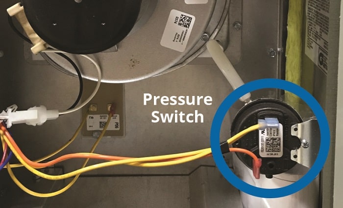
- Pressure Switch: This is the central component. It's a safety device that ensures the inducer motor is creating sufficient draft to safely vent combustion gases. It monitors the pressure differential and closes an electrical circuit, allowing the furnace to ignite.
- Inducer Motor (Draft Inducer): This motor creates a negative pressure (suction) within the combustion chamber and venting system, drawing in fresh air and exhausting combustion gases.
- Combustion Chamber: The enclosed space where the combustion process takes place.
- Vent Pipe: The pipe that carries combustion gases away from the furnace and out of your home.
- Hoses (Pressure Tubing): These flexible tubes connect the pressure switch to various points within the furnace, allowing it to sense pressure differences. They are typically made of silicone or rubber.
- Ports/Nipples: These are the connection points on the pressure switch, inducer motor housing, and combustion chamber where the hoses attach.
Key Specs to Consider:
- Pressure Switch Rating: Measured in inches of water column (in. w.c.), this indicates the pressure difference required to activate the switch. Common values range from -0.30 to -0.80 in. w.c. This is crucial for selecting a replacement switch.
- Hose Diameter: Ensure replacement hoses match the original diameter for a secure and airtight fit.
- Operating Voltage: Know the operating voltage of the pressure switch (usually 24VAC) to avoid electrical shock when testing.
Understanding Symbols
Furnace pressure switch hose diagrams typically use standardized symbols and conventions. Here's a breakdown:
- Lines: Solid lines represent hoses. Dashed lines might indicate electrical wiring. The thickness of the line usually doesn't hold any specific meaning other than clarity in the diagram.
- Colors: While not universally standardized, some diagrams use color-coding. For example, blue might represent hoses connected to the negative pressure side (suction side of the inducer motor), and red could indicate the positive pressure side (combustion chamber). Consult your specific diagram's legend for clarification.
- Icons/Shapes:
- A small rectangle or square usually represents the pressure switch itself.
- A circle with a fan symbol inside represents the inducer motor.
- A rectangle or irregular shape could depict the combustion chamber.
- Labels: Each component and hose is typically labeled with a unique identifier. This is crucial for accurate identification and troubleshooting. For example, you might see "PS1" for Pressure Switch 1, or "Hose A" connecting PS1 to the inducer motor.
Pay close attention to any accompanying legend or key on the diagram. This will explain any custom symbols or color codes used.
How It Works: The Pressure Switch in Action
The pressure switch's operation is relatively simple but vital for safety. Here's how it works in conjunction with the hoses:
- When the thermostat calls for heat, the control board signals the inducer motor to start.
- The inducer motor creates a negative pressure (suction) within the combustion chamber and vent pipe. This negative pressure is what draws in fresh air and exhausts combustion gases.
- One hose connects the pressure switch to the inducer motor housing, sensing this negative pressure. The other hose is often connected to the combustion chamber or a vent pipe location before the inducer motor.
- The pressure difference between these two points (typically a small negative pressure) causes a diaphragm inside the pressure switch to deflect.
- This deflection closes an electrical contact within the switch, completing a circuit.
- The control board detects the closed circuit, indicating that sufficient draft is present, and then allows the igniter to start and the gas valve to open.
- If the pressure drops below the switch's rating (e.g., due to a blocked vent or a failing inducer motor), the switch opens the circuit, shutting down the gas valve and preventing a potentially dangerous situation.
Real-World Use: Basic Troubleshooting Tips
Using the pressure switch hose diagram, you can perform some basic troubleshooting:
- Visual Inspection: Carefully examine all hoses for cracks, kinks, or disconnections. A loose or damaged hose can prevent the pressure switch from working correctly. Use the diagram to ensure each hose is connected to the correct port.
- Hose Obstructions: Disconnect the hoses and blow through them to check for obstructions. A blocked hose can prevent the pressure switch from sensing the correct pressure.
- Pressure Switch Testing: With the furnace off, you can use a multimeter to check the continuity of the pressure switch. It should be open when the inducer motor is off and closed when the inducer motor is running and creating draft. Always disconnect power to the furnace before testing electrical components.
- Manometer Test: Use a manometer (a device for measuring pressure) to verify that the inducer motor is creating sufficient draft and that the pressure switch is sensing the correct pressure difference. Connect the manometer to the ports used by the pressure switch hoses.
Common Issues and Solutions:
- Furnace won't ignite: Check for a blocked vent, a faulty inducer motor, or a bad pressure switch. Use the diagram to verify hose connections and test the pressure switch.
- Furnace shuts down prematurely: This could be caused by a fluctuating draft, a loose hose, or a failing pressure switch. Check the vent for obstructions and ensure all hoses are securely connected.
Safety Considerations
Working on a furnace involves potential hazards. Be extremely cautious and follow these safety guidelines:
- Disconnect Power: Always disconnect the power to the furnace at the breaker before performing any maintenance or troubleshooting.
- Gas Leaks: If you suspect a gas leak, immediately shut off the gas supply to the furnace and contact a qualified HVAC technician.
- Combustion Gases: Carbon monoxide is a colorless, odorless, and deadly gas. Ensure proper ventilation when working on the furnace.
- Hot Surfaces: Be aware that components like the heat exchanger and vent pipe can become extremely hot during operation. Avoid touching these surfaces.
- Pressure Switch Voltage: Be aware of the pressure switch voltage (24VAC is typical) and take precautions to avoid electric shock.
- Inducer Motor Blades: Be careful of the inducer motor blades, even when the unit is off. Some units store power, and the inducer fan can move unexpectedly.
High-Risk Components: The gas valve, heat exchanger, and vent pipe pose significant safety risks. If you are not comfortable working with these components, it's best to consult a qualified HVAC technician.
By understanding your furnace's pressure switch hose diagram, you can confidently tackle basic maintenance and troubleshooting tasks, potentially saving time and money. Remember to prioritize safety and consult a professional when dealing with complex issues or potentially hazardous components.
We have a sample furnace pressure switch hose diagram file available for download to help you further visualize the concepts discussed in this article. This diagram is a generic representation and may not perfectly match your specific furnace model, but it provides a valuable reference point.