
Fuse Box 2005 Ford Escape Fuse Diagram
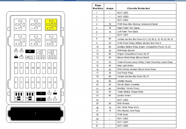
The 2005 Ford Escape fuse diagram is your roadmap to understanding and maintaining your vehicle's electrical system. Whether you're tackling a faulty radio, a malfunctioning window, or just trying to understand how your Escape is wired, this diagram is indispensable. This article provides an in-depth look at the fuse box, its components, and how to interpret the diagram, empowering you to perform basic troubleshooting and repairs safely and effectively. We'll cover everything from understanding fuse ratings to identifying potentially hazardous components, all while providing a downloadable diagram for your convenience. Having this knowledge not only saves you money on mechanic bills but also deepens your understanding of your vehicle's intricate workings.
Purpose of the Fuse Diagram
The primary purpose of the fuse diagram is to provide a clear and concise representation of the electrical circuits protected by each fuse and relay within the fuse box. It's essential for several reasons:
- Troubleshooting: Quickly identify which fuse corresponds to a specific component (e.g., headlights, power windows) to diagnose electrical problems.
- Repair: Replace blown fuses with the correct amperage rating to restore functionality.
- Modification: When adding aftermarket accessories (e.g., a new stereo system, auxiliary lighting), the diagram helps you safely tap into existing circuits or add new ones.
- Learning: Gain a better understanding of your vehicle's electrical system architecture.
Without a reliable fuse diagram, diagnosing electrical issues becomes a time-consuming and potentially damaging process. You'd be left guessing, which could lead to further problems or even safety hazards.
Key Specs and Main Parts
The 2005 Ford Escape actually has *two* main fuse boxes: the under-hood fuse box (also known as the Power Distribution Box) and the passenger compartment fuse box (typically located under the dashboard, on the driver's side). Each fuse box contains a variety of components:
- Fuses: These are sacrificial devices designed to protect electrical circuits from overcurrent. They contain a thin wire that melts and breaks the circuit when the current exceeds a certain threshold. Fuse ratings are measured in amperes (A). Common ratings range from 5A to 30A.
- Relays: Relays are electrically operated switches that allow a low-current circuit to control a high-current circuit. They're used for components that draw a significant amount of power, such as headlights, the starter motor, and the fuel pump.
- Circuit Breakers: Similar to fuses, but circuit breakers can be reset manually or automatically after an overcurrent condition is resolved. They are less common in modern vehicles but may be present for certain high-demand circuits.
- Fuse Puller: A small plastic tool used to safely remove fuses without damaging them or the fuse box.
The 2005 Escape utilizes blade-type fuses, also known as spade fuses or plug-in fuses. These fuses are color-coded according to their amperage rating, making it easier to identify the correct replacement. The color coding system is as follows (though always double-check the number printed on the fuse):
- Gray: 2A
- Violet: 3A
- Pink: 4A
- Orange: 5A
- Brown: 7.5A
- Red: 10A
- Blue: 15A
- Yellow: 20A
- Clear: 25A
- Green: 30A
Important Note: Always replace a blown fuse with one of the *exact* same amperage rating. Using a fuse with a higher rating can overload the circuit and cause damage or even a fire.
Symbols and Diagram Interpretation
Fuse diagrams typically use a grid layout to represent the physical arrangement of fuses and relays in the fuse box. Each position in the grid corresponds to a specific fuse or relay, and the diagram will indicate which circuit it protects. Here's what you might find:
- Fuse Numbers: Each fuse is assigned a unique number (e.g., F1, F2, F3, etc.) to identify it on the diagram.
- Component Names: Next to each fuse number, the diagram will list the component or circuit that the fuse protects (e.g., "Headlights," "Power Windows," "Fuel Pump").
- Amperage Rating: The amperage rating of each fuse is also indicated on the diagram (e.g., "15A," "20A").
- Relay Symbols: Relays are often represented by a square or rectangle with the letter "R" inside (e.g., R1, R2, R3, etc.). The diagram will also indicate the function of each relay.
- Lines and Connections: Lines may be used to indicate connections between fuses, relays, and other components.
Some diagrams may also include symbols for ground connections, voltage sources, and other electrical components. Understanding these symbols allows you to trace the flow of electricity through the circuit and identify potential points of failure.
Key Tip: Take your time and carefully compare the fuse diagram to the actual fuse box in your vehicle. Pay attention to the fuse numbers, component names, and amperage ratings. A flashlight can be incredibly helpful in illuminating the fuse box and making it easier to read the diagram.
How It Works
The electrical system of your 2005 Ford Escape is designed to deliver power from the battery to various components throughout the vehicle. Fuses act as safety valves within these circuits. When an overcurrent condition occurs (e.g., due to a short circuit or a malfunctioning component), the fuse's internal wire melts, breaking the circuit and preventing damage to the wiring and components. Relays, on the other hand, act as remote control switches. The vehicle's computer or a manual switch sends a small amount of current to the relay, which then closes a high-current circuit, allowing power to flow to the desired component. This prevents high current from flowing through the control switch, protecting it from damage.
Think of it like a water system: the battery is the reservoir, the wires are the pipes, the components are the destinations, the fuses are pressure relief valves and the relays are valves operated remotely.
Real-World Use: Basic Troubleshooting
Here's a basic troubleshooting scenario:
- Symptom: Your headlights are not working.
- Step 1: Consult the fuse diagram to identify the fuse(s) that protect the headlights. Note the fuse number and amperage rating.
- Step 2: Locate the under-hood fuse box.
- Step 3: Use the fuse puller to remove the headlight fuse(s).
- Step 4: Inspect the fuse(s) for damage. A blown fuse will have a broken or melted filament.
- Step 5: If the fuse is blown, replace it with a new fuse of the *same* amperage rating.
- Step 6: Test the headlights. If they still don't work, there may be a more serious problem with the wiring, the headlight bulbs, or the headlight switch. Further diagnosis is required.
Important Tip: If a fuse blows repeatedly, there is likely a short circuit or an overload in the affected circuit. Do not simply replace the fuse with a higher amperage rating, as this could cause serious damage or a fire. Instead, take your vehicle to a qualified mechanic for diagnosis and repair.
Safety Precautions
Working with automotive electrical systems can be dangerous if proper precautions are not taken. Here are some important safety guidelines:
- Disconnect the Battery: Before working on any electrical components, disconnect the negative (-) terminal of the battery. This will prevent accidental short circuits and electrical shocks.
- Use Insulated Tools: Use tools with insulated handles to protect yourself from electrical shock.
- Wear Safety Glasses: Wear safety glasses to protect your eyes from debris or sparks.
- Avoid Water: Never work on electrical components in wet or damp conditions.
- Be Aware of High-Voltage Components: Be especially careful around components that operate at high voltage, such as the ignition system and the air conditioning system. These components can deliver a potentially lethal shock. The air conditioning system uses pressurized refrigerant – improper handling can result in serious injury.
Disclaimer: The information provided in this article is for informational purposes only and should not be considered a substitute for professional advice. If you are not comfortable working on your vehicle's electrical system, take it to a qualified mechanic.
Now that you understand the importance of the 2005 Ford Escape fuse diagram, its key components, and how to use it for basic troubleshooting, you're well-equipped to maintain your vehicle's electrical system. Remember to always prioritize safety and consult a professional if you encounter any complex issues.
We have the full 2005 Ford Escape fuse diagram file available for download. Use it wisely and safely!