Fuse Box Diagram 2008 Nissan Rogue
The fuse box diagram for your 2008 Nissan Rogue is an invaluable resource for any DIY mechanic or car enthusiast. It's more than just a piece of paper; it's a roadmap to your vehicle's electrical system, enabling you to diagnose problems, perform repairs, and even add aftermarket accessories with confidence. This article delves into the specifics of the 2008 Rogue's fuse box diagram, providing the knowledge you need to understand and utilize it effectively.
Purpose of the Fuse Box Diagram
Why is understanding the fuse box diagram so important? Several reasons stand out:
- Troubleshooting Electrical Issues: When an electrical component fails – a headlight, the radio, or even the windshield wipers – the first place to check is the fuse box. The diagram helps you quickly locate the correct fuse associated with that component.
- Performing Repairs: Replacing a blown fuse is a simple task, but identifying the correct one is crucial. The diagram prevents you from pulling the wrong fuse, which could disrupt other systems.
- Adding Aftermarket Accessories: Want to install a new stereo system, auxiliary lights, or a dashcam? Knowing the layout of the fuse box and the current ratings of each circuit allows you to tap into the electrical system safely and effectively.
- Understanding Vehicle Systems: Studying the fuse box diagram provides a deeper understanding of how the various electrical systems in your Rogue are interconnected.
Key Specs and Main Parts
The 2008 Nissan Rogue typically has two fuse box locations:
- Interior Fuse Box: Located under the dashboard on the driver's side. This box primarily houses fuses for interior components like the radio, lights, and power windows.
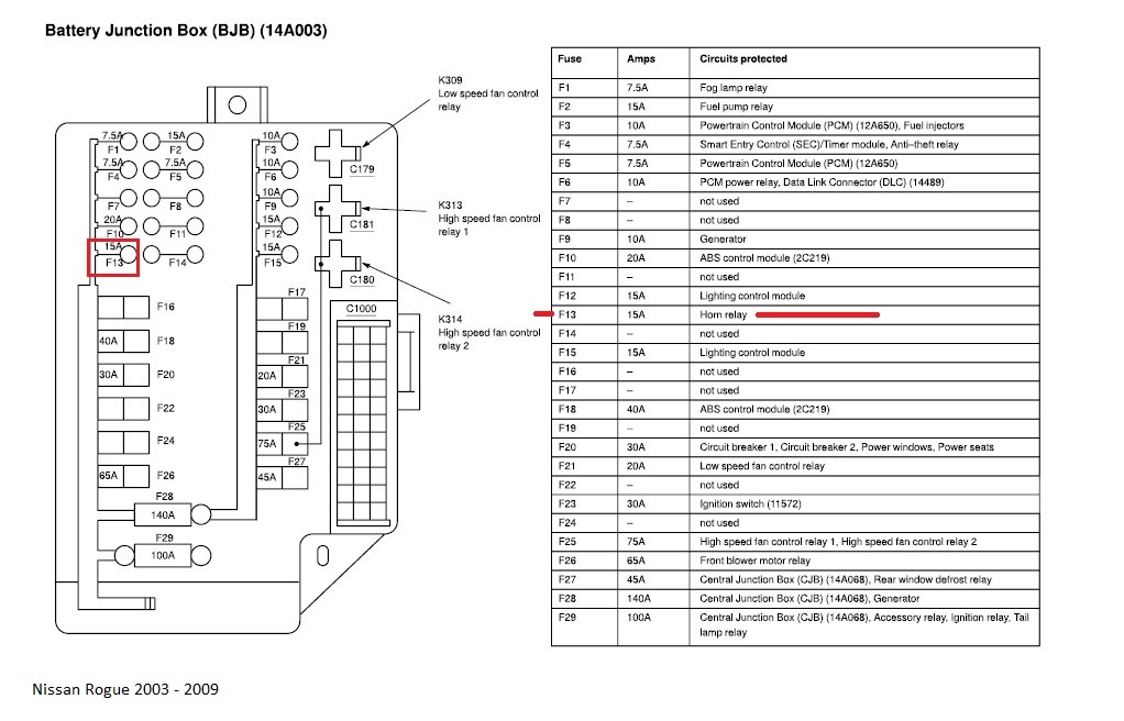
- Engine Compartment Fuse Box: Situated in the engine bay, usually near the battery. This box contains fuses for critical engine components, headlights, and the ABS (Anti-lock Braking System).
Important Specifications: Each fuse is rated for a specific amperage, indicated by a number printed on the fuse itself (e.g., 5A, 10A, 15A). This rating represents the maximum current that the fuse can safely handle before it blows, protecting the circuit from overload. Using a fuse with a higher amperage rating than specified is extremely dangerous and can lead to overheating, fire, and damage to electrical components.
The diagram will clearly label each fuse location, along with its amperage rating and the component it protects. Furthermore, it may also show the location and function of relays which are electromechanical switches that allow a low-current circuit to control a high-current circuit, protecting the switching device from excessive current draw. Understanding the roles of both fuses and relays is critical.
Decoding the Symbols: Lines, Colors, and Icons
Fuse box diagrams use a standardized set of symbols to represent different components and connections. Understanding these symbols is essential for interpreting the diagram correctly.
- Lines: Solid lines typically represent wiring. Thicker lines might indicate higher current-carrying capacity. Dashed lines can represent grounding points or less critical connections.
- Colors: The color of the wiring on the diagram is not always reflective of the actual wiring color in your vehicle, but it can still be useful. However, be aware that wire colors can vary slightly depending on the trim level and production date of your Rogue.
- Icons: Standardized icons are used to represent various components, such as:
- Headlight Icon: Represents the headlight circuit.
- Radio Icon: Represents the radio circuit.
- Windshield Wiper Icon: Represents the windshield wiper circuit.
- ABS Icon: Represents the Anti-lock Braking System circuit.
- Power Window Icon: Represents the power window circuit.
Pay close attention to the abbreviations used on the diagram. For example, "IGN" typically stands for Ignition, "ACC" for Accessory, and "ECU" for Engine Control Unit. Consulting your owner's manual is invaluable for finding the correct meaning of these abbreviations, or doing a quick search online.
How It Works: Electrical Circuits and Fuse Protection
The fuse box is the central distribution point for electrical power in your vehicle. Each circuit is protected by a fuse, which acts as a sacrificial component. When excessive current flows through a circuit (due to a short circuit, overload, or component failure), the fuse melts, breaking the circuit and preventing damage to other components. The fuse contains a small wire designed to melt at a specific current. This protects the wires from overheating and potentially starting a fire.
A blown fuse indicates a problem in the circuit it protects. Simply replacing the fuse without addressing the underlying issue will likely result in the new fuse blowing as well. Troubleshooting the cause of the blown fuse is crucial. Never replace a fuse with one of a higher amperage rating, as this can bypass the safety mechanism and lead to serious damage or fire.
Real-World Use: Basic Troubleshooting Tips
Here's how to use the fuse box diagram to troubleshoot common electrical problems:
- Identify the Symptom: Determine which component is not working (e.g., the radio is dead, the headlights are not turning on).
- Consult the Diagram: Locate the fuse associated with the malfunctioning component using the fuse box diagram.
- Inspect the Fuse: Visually inspect the fuse. A blown fuse will typically have a broken filament or a darkened appearance. You can also use a multimeter to test the fuse for continuity. Set the multimeter to the continuity setting (often represented by a sound wave symbol) and place the probes on each end of the fuse. If the multimeter beeps or displays a low resistance reading, the fuse is good. If it doesn't, the fuse is blown.
- Replace the Fuse: If the fuse is blown, replace it with a new fuse of the exact same amperage rating.
- Test the System: After replacing the fuse, test the component to see if it's working.
- If the Fuse Blows Again: If the new fuse blows immediately or shortly after replacement, there is a more serious underlying problem that needs to be diagnosed by a qualified mechanic. This could be a short circuit, a faulty component, or a wiring issue.
Safety Precautions
Working with automotive electrical systems can be dangerous. Always take the following precautions:
- Disconnect the Battery: Before working on any electrical components, disconnect the negative terminal of the battery to prevent accidental short circuits.
- Use the Right Tools: Use insulated tools designed for automotive electrical work.
- Never Bypass a Fuse: Never attempt to bypass a fuse by using a wire or other conductive material. This is extremely dangerous and can cause serious damage or fire.
- Be Cautious Around High-Voltage Components: Some components, such as the ignition system, operate at high voltages. Avoid touching these components with the ignition on.
- Consult a Professional: If you are not comfortable working with automotive electrical systems, consult a qualified mechanic.
The components related to the SRS (Supplemental Restraint System, airbags) are particularly sensitive and should only be handled by trained professionals. Incorrect handling of these systems can result in accidental airbag deployment, causing serious injury.
We have a copy of the 2008 Nissan Rogue fuse box diagram available for download. This detailed diagram will be an invaluable resource for your troubleshooting and repair efforts, allowing you to work on your vehicle's electrical system with confidence and precision.