
Fuse Box Diagram For 2004 Ford Explorer
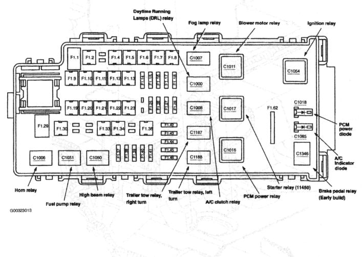
Alright, let's dive into the fuse box diagram for your 2004 Ford Explorer. Whether you're tackling electrical repairs, adding aftermarket accessories, or just trying to understand your vehicle's inner workings, a solid grasp of this diagram is essential. Think of it as the electrical roadmap for your Explorer, guiding you through the labyrinth of circuits and components. We’re going to cover everything from the key specs to troubleshooting, keeping things practical and understandable.
Purpose of the Fuse Box Diagram
Why bother with a fuse box diagram? Well, several reasons:
- Repairs: When something electrical malfunctions – a blown fuse is the first place to look. The diagram tells you exactly which fuse controls what circuit.
- Accessory Installation: Adding a new stereo, lights, or other accessories requires tapping into the electrical system. Knowing the fuse layout prevents overloading circuits and potential damage.
- Troubleshooting: Electrical problems can be tricky. The diagram helps you isolate the issue to a specific circuit, simplifying the diagnostic process.
- General Knowledge: Understanding the electrical system enhances your overall vehicle knowledge and empowers you to perform basic maintenance and repairs yourself.
Key Specs and Main Parts
Your 2004 Ford Explorer actually has two main fuse boxes:
- Battery Junction Box (BJB): Located under the hood, typically on the driver's side, near the battery. This is the primary distribution point for power, housing high-amperage fuses and relays that control major systems like the engine, transmission, and lighting.
- Central Junction Box (CJB): Located inside the cabin, usually under the dashboard on the driver's side. This box houses fuses and relays for interior components like the radio, power windows, and climate control. Access might require removing a trim panel.
Symbols: Decoding the Diagram
Fuse box diagrams aren't just random lines and numbers; they use a standardized set of symbols to represent electrical components and connections. Here's a breakdown of common symbols you'll encounter:
- Fuses: Typically represented by a zigzag line enclosed in a rectangle or square. The amperage rating is usually printed next to the symbol.
- Relays: Usually shown as a rectangle with terminals labeled. A relay is an electrically operated switch, allowing a low-current circuit to control a high-current circuit. This is crucial for things like headlights and starter motors.
- Wires: Straight lines represent wires. Colors are often indicated with abbreviations (e.g., RD for red, BK for black). Wire gauge, indicating thickness and current-carrying capacity, is generally not shown on the fuse box diagram itself, but it's crucial information for any wiring modifications.
- Grounds: Usually depicted as a downward-pointing arrow connected to horizontal lines. These indicate where the circuit connects to the vehicle's chassis for grounding.
- Circuit Numbers: Each circuit is usually assigned a number, which may be referenced elsewhere in the vehicle's wiring diagrams.
How It Works: The Electrical Flow
Understanding how the electrical system works is crucial for using the fuse box diagram effectively. Electricity flows from the battery, through a fuse or relay (or both), and then to the component it powers (e.g., a headlight bulb, a motor, a control module). The fuse acts as a safety device, protecting the circuit from overcurrent. If the current exceeds the fuse's rating, the fuse's internal element melts, breaking the circuit and preventing damage. Relays, on the other hand, are used to control high-current circuits with a low-current signal. For example, the starter relay allows the ignition switch (which handles relatively low current) to control the high current needed to power the starter motor. A typical scenario involves the ignition switch activating the relay coil. When the coil is energized, it creates a magnetic field that pulls the relay contacts together, completing the circuit to the starter motor.
The diagram will show you which components are connected to each fuse. For example, a fuse labeled "Interior Lights" might power the dome light, map lights, and courtesy lights. If all those lights suddenly stop working, you know to check that specific fuse first.
Real-World Use: Basic Troubleshooting
Here’s how to use the fuse box diagram for basic troubleshooting:
- Identify the Symptom: What's not working? A blown fuse is often a symptom, not the root cause.
- Consult the Diagram: Locate the fuse that controls the malfunctioning component.
- Inspect the Fuse: Visually inspect the fuse. A blown fuse will have a broken filament. You can also use a multimeter to check for continuity.
- Replace the Fuse: If the fuse is blown, replace it with a fuse of the exact same amperage rating.
- Test: Turn on the component. If the fuse blows again immediately, there's likely a short circuit somewhere in the system.
Example: Your 2004 Explorer's radio suddenly stops working. First, find the fuse box diagram (remember, we have a downloadable version for you!). Locate the fuse labeled "Radio" (or something similar). Inspect the fuse. If it's blown, replace it with a fuse of the correct amperage. If the radio now works, you're done. If the fuse blows again, there's a problem with the radio wiring or the radio itself.
Safety: Handle with Care
Working with electrical systems can be dangerous. Here are some crucial safety precautions:
- Disconnect the Battery: Before working on any electrical system, disconnect the negative (-) battery cable. This prevents accidental shorts and electrical shocks.
- Use the Right Tools: Use insulated tools designed for electrical work.
- Never Bypass a Fuse: Never replace a fuse with a higher amperage rating or use a piece of wire to bypass a fuse. This can cause serious damage or even a fire.
- Be Careful with Relays: Relays can get hot, especially when they're malfunctioning. Let them cool down before handling them.
- High-Risk Components: Be particularly cautious when working around the airbag system, ABS system, and fuel injection system. These systems require specialized knowledge and tools. Incorrect handling can lead to serious injury.
Ultimately, using the fuse box diagram for your 2004 Ford Explorer is a powerful tool for diagnosing and fixing electrical problems. By understanding the symbols, the circuit flow, and the safety precautions, you can confidently tackle many electrical repairs and modifications yourself. Remember to always double-check your work and consult a professional if you're unsure about anything.
Ready to get started? We have the complete fuse box diagram file for your 2004 Ford Explorer available for download. This detailed diagram will be your best friend when troubleshooting electrical issues.