Fuse Box Diagram For 2005 Jeep Grand Cherokee
Let's dive into the fuse box diagram for the 2005 Jeep Grand Cherokee. This isn't just a pretty picture; it's your roadmap to understanding and troubleshooting your vehicle's electrical system. Whether you're tackling a simple blown fuse, installing aftermarket accessories, or diagnosing a more complex electrical gremlin, having a solid grasp of this diagram is crucial.
Purpose of the Fuse Box Diagram
The primary purpose of a fuse box diagram is to provide a clear and concise representation of the various electrical circuits in your 2005 Jeep Grand Cherokee. It allows you to quickly identify which fuse protects which component. This is invaluable for:
- Troubleshooting Electrical Issues: When a component malfunctions, the first step is often to check its corresponding fuse.
- Installing Aftermarket Accessories: Safely tapping into the electrical system requires knowing which circuits can handle the additional load.
- Understanding Vehicle Systems: The diagram provides insight into how different components are interconnected and protected.
- Preventing Further Damage: Replacing a blown fuse with one of the correct amperage rating prevents potentially damaging overloads.
Key Specs and Main Parts
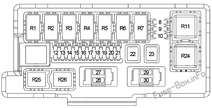
Your 2005 Jeep Grand Cherokee actually has two main fuse boxes. Knowing their locations is key:
- The Power Distribution Center (PDC): Located under the hood, typically near the battery. This houses high-amperage fuses and relays for critical systems like the engine, transmission, and ABS.
- The Junction Block (JB): Located inside the cabin, usually under the dashboard on the driver's side. This protects circuits for interior components like the radio, lights, and power windows.
The diagram will usually list each fuse by number, amperage rating, and the component it protects. Key specs you'll find include:
- Fuse Number: A unique identifier for each fuse.
- Amperage Rating (Amps or A): Indicates the maximum current a fuse can handle before blowing. Common ratings are 5A, 10A, 15A, 20A, 25A, 30A, and higher. Using the wrong amperage fuse can be very dangerous.
- Component Protected: A brief description of the component powered by that circuit (e.g., "Radio," "Headlights," "Fuel Pump").
- Relays: Electrically operated switches that control high-current circuits. These are also often shown on the diagram and control things like the starter motor, fuel pump, and air conditioning compressor.
Understanding Fuse Box Symbols and Conventions
Fuse box diagrams aren't just random lines and squares. They use standardized symbols to represent different components. Here’s a breakdown of common elements:
- Fuses: Typically represented by a straight line between two terminals or a stylized "S" shape.
- Relays: Shown as a square or rectangle with terminals representing the coil and the switch contacts. You might see both normally open (NO) and normally closed (NC) contacts.
- Wires: Solid lines represent wires connecting components. Dashed lines might indicate grounding points or connections to other modules.
- Grounds: A symbol resembling an upside-down Christmas tree or a series of progressively smaller lines.
- Connectors: Represented by circles or squares, indicating where wires connect to each other or to components.
Color-coding can also be used, but this is more common on wiring diagrams than fuse box diagrams. If colors *are* present, they usually indicate the wire color (e.g., Red for positive, Black for ground, etc.). Note that wire colors can vary slightly based on trim level and options packages.
How It Works: The Electrical Protection System
The entire purpose of the fuse box is to protect the electrical system from overcurrent conditions. An overcurrent can happen for several reasons:
- Short Circuit: A direct connection between a positive wire and ground. This causes a very high current flow.
- Overload: Too many devices drawing power from the same circuit.
- Component Failure: A faulty component drawing excessive current.
When an overcurrent occurs, the thin wire inside the fuse heats up rapidly and melts, breaking the circuit. This prevents further current flow and protects the wiring and components from damage. The amperage rating of the fuse is crucial. If you use a fuse with a higher amperage rating than specified, it might not blow quickly enough to protect the circuit, potentially leading to a fire.
Relays, on the other hand, act as electrically controlled switches. They are used to control high-current circuits with a low-current signal. For example, the starter motor requires a lot of current to operate. The ignition switch, however, can only handle a small amount of current. The relay allows the ignition switch to activate the starter motor by controlling the high-current circuit.
Real-World Use: Basic Troubleshooting
Here's how you might use the fuse box diagram to troubleshoot a common problem:
Scenario: Your 2005 Grand Cherokee's radio suddenly stops working.
- Consult the Diagram: Locate the fuse box diagram (usually found in the owner's manual or online).
- Identify the Radio Fuse: Find the fuse labeled "Radio" or "Audio System" on the diagram. Note its fuse number and amperage rating.
- Locate the Fuse: Open the relevant fuse box (probably the Junction Block inside the cabin) and find the fuse corresponding to the number you identified.
- Inspect the Fuse: Visually inspect the fuse. A blown fuse will have a broken filament or a blackened appearance. You can also use a multimeter to check for continuity. A good fuse will have continuity (a reading of 0 ohms).
- Replace the Fuse: If the fuse is blown, replace it with a new fuse of the exact same amperage rating.
- Test the System: Turn on the radio to see if it works.
Important Notes:
- If the new fuse blows immediately, there's likely a short circuit in the radio wiring or the radio itself. Further diagnosis is needed.
- Always use the correct amperage rating. Using a higher amperage fuse can damage the wiring and components.
- If you are unsure about any electrical repairs, consult a qualified mechanic.
Safety: Handling Risky Components
Working with automotive electrical systems can be dangerous. Here are some key safety precautions:
- Disconnect the Battery: Before working on any electrical components, disconnect the negative battery cable. This prevents accidental short circuits.
- Use Proper Tools: Use insulated tools to avoid electric shock.
- Avoid Water: Never work on electrical systems in wet conditions.
- Be Careful with High-Voltage Components: The ignition system and certain sensors can operate at high voltages. Avoid touching these components while the engine is running.
- Airbags: Airbag systems have their own dedicated fuses and wiring. Do not tamper with airbag wiring unless you are a qualified technician. Accidental deployment can cause serious injury.
- Relays Can Be Tricky: Be aware that some relays supply power to critical components. Improperly removing or manipulating these can lead to the vehicle not starting or other unexpected behavior. Always consult the diagram before removing relays.
Remember, electricity can be hazardous. When in doubt, seek professional help.
Fuse Box Diagram Download
To help you even further, we have a high-resolution, printable fuse box diagram for the 2005 Jeep Grand Cherokee. You can download it by clicking [link to download here]. This diagram will provide you with the information you need to safely and effectively troubleshoot your vehicle's electrical system. Remember to always prioritize safety and consult a professional if you are unsure about any repairs.