Fuse Box Diagram For 2005 Mercury Grand Marquis
If you're tackling electrical repairs, modifications, or even just trying to understand your 2005 Mercury Grand Marquis's electrical system, the fuse box diagram is your Rosetta Stone. Without it, you're essentially poking around blindly, hoping not to short something out or misdiagnose a problem. This guide will provide a comprehensive breakdown of that diagram, turning you from a guessing amateur into a confident troubleshooter.
Purpose of the Fuse Box Diagram
The fuse box diagram, sometimes referred to as a fuse panel layout, is a visual representation of your vehicle's electrical protection system. Its primary purpose is to identify the location of each fuse and relay, along with its corresponding circuit. Why is this important? Well, consider these scenarios:
- Electrical Repair: A malfunctioning taillight, a dead radio, or even a non-starting engine could be the result of a blown fuse. The diagram allows you to quickly locate and identify the fuse responsible for that circuit.
- Modifications: Adding aftermarket accessories like a new stereo system, auxiliary lights, or a trailer brake controller requires tapping into the existing electrical system. The diagram helps you determine which circuits are suitable for your modifications and how to properly protect them.
- Understanding the System: Even if you're not actively repairing or modifying anything, the diagram offers a valuable insight into how your vehicle's electrical system is organized. This knowledge can be invaluable for preventative maintenance and diagnosing potential problems before they become major headaches.
Key Specs and Main Parts of the 2005 Grand Marquis Fuse Boxes
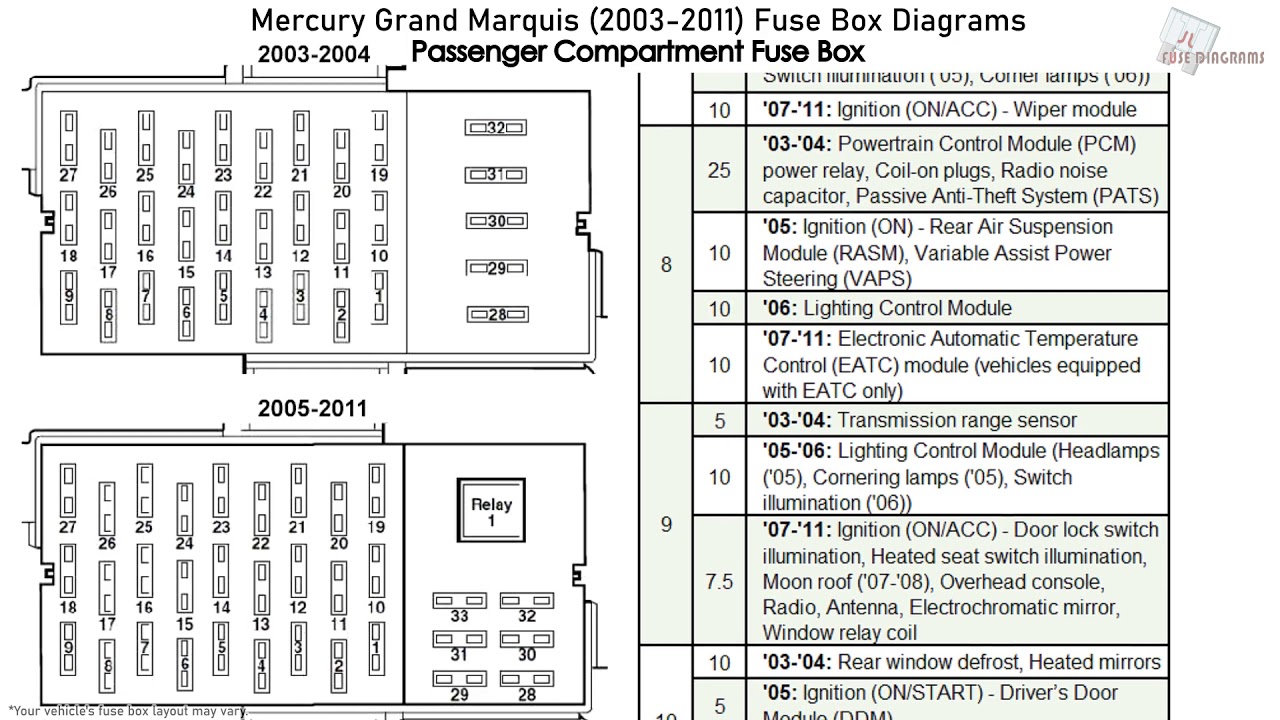
Your 2005 Grand Marquis has two main fuse boxes: one located inside the passenger compartment (typically under the dashboard on the driver's side) and another under the hood, usually near the engine. Here’s a breakdown of what to expect:
- Passenger Compartment Fuse Box: This box generally handles circuits related to interior functions like the radio, lights, power windows, door locks, and instrument panel.
- Under-Hood Fuse Box: This box contains fuses and relays for critical engine and drivetrain components like the fuel pump, ignition system, cooling fan, and anti-lock braking system (ABS).
Each fuse box consists of the following main parts:
- The Housing: The physical box itself, typically made of plastic and designed to protect the fuses and relays from the elements.
- Fuses: Small, sacrificial devices designed to protect electrical circuits from overcurrent conditions. Fuses come in various amperage ratings (measured in amps, A), and the correct rating is crucial for proper protection. Using a fuse with a higher amperage rating than specified can allow excessive current to flow, potentially damaging components or even causing a fire.
- Relays: Electrically operated switches that allow a low-current circuit to control a high-current circuit. Relays are used to switch on and off components that require a significant amount of power, such as the starter motor, headlights, and air conditioning compressor.
- The Diagram Label: Typically located on the inside of the fuse box cover, this label provides the vital information you need to identify each fuse and relay. The diagram itself may be a printed sticker or a molded representation in the plastic of the lid.
Understanding Fuse Box Symbols
Fuse box diagrams use a variety of symbols, colors, and lines to convey information. Here’s a guide to help you decipher them:
- Lines: Solid lines typically represent the electrical circuits, while dashed lines may indicate ground connections or connections to other parts of the system.
- Colors: Wire colors are often indicated on the diagram, helping you trace the circuit if necessary. Common colors include red (power), black (ground), and various other colors for specific circuits.
- Icons: Icons represent the component that the fuse or relay protects. For example:
- A lightbulb icon indicates a fuse for lights.
- A speaker icon indicates a fuse for the radio.
- A steering wheel icon indicates a fuse for power steering.
- An engine icon indicates a fuse for engine management system.
- Amperage Ratings: Each fuse location will have a number associated with it, indicating the amperage rating of the fuse that should be installed in that position. This is critical – always replace a blown fuse with one of the exact same amperage rating.
- Relay Labels: Relays are typically labeled with abbreviations indicating their function, such as "FUEL PUMP RELAY," "A/C CLUTCH RELAY," or "STARTER RELAY."
How It Works: The Fuse Protection System
The electrical system is designed to power all the various components of your car. A fuse is a deliberately weak point in each electrical circuit. Think of it as an electrical safety valve. It contains a thin wire that is designed to melt and break the circuit if the current flowing through it exceeds its rated amperage.
When a short circuit or overload occurs (e.g., due to a faulty component or a wiring issue), the excessive current flows through the fuse. This causes the fuse element (the thin wire) to overheat and melt, breaking the circuit and preventing damage to other components. The blown fuse effectively shuts down the affected circuit, protecting it from further damage.
Real-World Use: Basic Troubleshooting Tips
Here's how to use the fuse box diagram for basic troubleshooting:
- Identify the Problem: Determine which component is not working (e.g., the radio, headlights, etc.).
- Consult the Diagram: Locate the fuse box diagram and find the fuse or relay associated with the malfunctioning component.
- Inspect the Fuse: Visually inspect the fuse. A blown fuse will typically have a broken filament (the thin wire inside the fuse). You can also use a multimeter set to continuity mode to test the fuse. A good fuse will have continuity (the multimeter will beep), while a blown fuse will not.
- Replace the Fuse: If the fuse is blown, replace it with a new fuse of the correct amperage rating.
- Test the Circuit: After replacing the fuse, test the affected component to see if it is now working.
- If the Fuse Blows Again: If the new fuse blows immediately or shortly after being replaced, this indicates a more serious problem, such as a short circuit or a faulty component. Further diagnosis by a qualified mechanic is recommended.
Safety Precautions
Working with electrical systems can be dangerous. Here are some crucial safety precautions:
- Disconnect the Battery: Before working on the electrical system, disconnect the negative (-) terminal of the battery. This will prevent accidental shorts and potential electric shock.
- Use the Correct Fuse: Always replace a blown fuse with one of the exact same amperage rating. Using a fuse with a higher amperage rating can bypass the protection mechanism and potentially cause a fire.
- Avoid Water: Never work on the electrical system in wet or damp conditions.
- Be Careful with Wires: Handle wires carefully and avoid pulling or tugging on them. Damaged wires can cause shorts and other electrical problems. Especially avoid poking around in the wiring harnesses; you could damage something worse.
- High Current Components: Be extremely careful around components such as the starter solenoid and alternator. These components carry very high currents and can be dangerous if shorted. The relays and fuses controlling them are equally dangerous.
Remember, if you're not comfortable working with electrical systems, it's always best to consult a qualified mechanic.
We have a downloadable version of the 2005 Mercury Grand Marquis fuse box diagram available. This diagram provides a detailed layout of both the interior and under-hood fuse boxes, including fuse locations, amperage ratings, and the circuits they protect. You can use it in conjunction with this article for effective troubleshooting.