Fuse Box Diagram For 2006 Dodge Charger Rt
Let's dive into the fuse box diagram for your 2006 Dodge Charger RT. This isn't just a piece of paper; it's your roadmap to understanding and troubleshooting your car's electrical system. Whether you're dealing with a faulty window, upgrading your sound system, or just trying to understand how everything is wired, knowing your way around the fuse box is essential. We'll break down the key specs, symbols, and how the system works, empowering you to diagnose and fix electrical issues safely and effectively.
Purpose of the Fuse Box Diagram
Why bother with this diagram? Several reasons:
- Troubleshooting Electrical Issues: The most common use is pinpointing the cause of a malfunctioning component. If your headlights aren't working, the diagram tells you which fuse to check.
- Performing Repairs: When replacing a component, you might need to disconnect power to certain circuits. The diagram identifies which fuses control those circuits.
- Adding Aftermarket Accessories: Installing a new stereo, amplifier, or auxiliary lights? The diagram shows you available circuits and where to tap into power safely.
- Understanding Vehicle Systems: Gaining a deeper knowledge of how your car's electrical systems are organized.
Think of the diagram as a translator between you and your car's electrical language. It provides a visual representation of a complex system, making it accessible and understandable.
Key Specs and Main Parts of the 2006 Dodge Charger RT Fuse Box
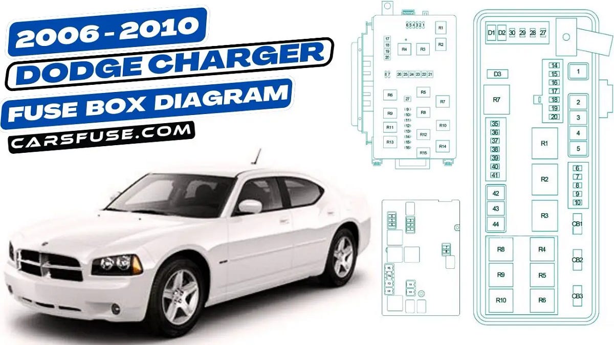
The 2006 Dodge Charger RT actually has two main fuse boxes: the Power Distribution Center (PDC) under the hood and the Central Junction Box (CJB) inside the cabin, typically located on the driver's side, often behind a panel near the steering wheel or beneath the dashboard. Both are critical.
Power Distribution Center (PDC)
The PDC handles high-current circuits and relays. It's the main distribution point for power coming from the battery.
- Location: Under the hood, usually near the battery.
- Content: Houses fuses, relays, and sometimes circuit breakers.
- Purpose: Protects major components like the engine control unit (ECU), starter motor, alternator, and high-power lighting systems.
Central Junction Box (CJB)
The CJB deals with lower-current circuits that power interior components and control systems.
- Location: Inside the cabin, usually on the driver's side.
- Content: Houses fuses and sometimes relays.
- Purpose: Protects components like the radio, power windows, door locks, instrument cluster, and interior lighting.
Key Specifications to Consider:
- Fuse Ampere Rating: Each fuse is rated for a specific current (amps). Never replace a fuse with one of a higher rating, as this could cause serious damage or even a fire. Always use the correct amperage rating.
- Fuse Type: The Charger RT uses blade-type fuses. Familiarize yourself with the different sizes (ATO, Mini, Maxi) and their respective ratings.
- Relay Type: Various relays control different circuits. Knowing which relay controls which system is essential for troubleshooting.
Understanding the Symbols: Lines, Colors, and Icons
Fuse box diagrams use a standardized set of symbols to represent electrical components and connections. Here's a breakdown of common symbols:
- Fuses: Typically represented by a rectangle with a wavy line inside. The amperage rating is usually printed next to the symbol.
- Relays: Depicted as a square or rectangle with a coil symbol inside, along with contact points. Understanding relay operation is key to diagnosing more complex electrical problems.
- Circuit Breakers: Showed as a rectangle with a switch symbol inside. Unlike fuses, circuit breakers can be reset after tripping.
- Ground Points: Illustrated by a symbol that looks like an inverted, stacked pyramid. Proper grounding is crucial for the entire electrical system to function correctly.
- Wiring: Lines represent wires. Different colors may indicate different functions or voltage levels, although this isn't always explicitly noted on the diagram itself but is generally standard automotive wiring color-coding. A dashed line typically indicates a shielded wire.
Color Codes: While the diagram itself might not always use color-coded lines, understanding automotive wiring color conventions is very helpful. For example:
- Red: Typically indicates a power wire, often directly from the battery.
- Black: Usually indicates ground.
- Other Colors: Vary depending on the specific circuit. For instance, blue might be used for lighting, or green for certain sensor signals. Refer to a wiring diagram for the specific year and model for detailed color codes.
How It Works: The Electrical Flow
Understanding how the electrical system functions is vital for effective troubleshooting. The basic principle is simple: electricity flows from the battery, through a circuit protected by a fuse, and to the component it powers. Here's a simplified breakdown:
- Battery: Provides the initial electrical power.
- Fuse: Protects the circuit from overcurrent. If too much current flows (e.g., due to a short circuit), the fuse melts, breaking the circuit and preventing damage.
- Switch/Relay: Controls the flow of electricity to the component. A switch is manually operated, while a relay is electrically operated (often by the ECU).
- Component: The device that uses the electricity (e.g., a headlight, motor, or sensor).
- Ground: Provides a return path for the electricity back to the battery, completing the circuit.
Relays are electromagnetic switches. A small current activates the relay's coil, which pulls a contact closed, allowing a larger current to flow through the main circuit. Relays are used to control high-current components with low-current signals from the ECU or other control modules.
Real-World Use: Basic Troubleshooting Tips
Let's say your power windows aren't working. Here's how you can use the fuse box diagram to troubleshoot:
- Consult the Diagram: Locate the fuse labeled "Power Windows" in the CJB diagram.
- Identify the Fuse: Find the physical fuse in the CJB based on its location in the diagram.
- Inspect the Fuse: Visually check the fuse. If the filament inside is broken, the fuse is blown.
- Test the Fuse (Optional): Use a multimeter to test for continuity across the fuse. A blown fuse will show no continuity.
- Replace the Fuse: Replace the blown fuse with a new fuse of the exact same amperage rating.
- Test the System: Try the power windows. If they still don't work, there might be another issue (e.g., a faulty motor, switch, or wiring problem). In that case, you will need to consult wiring diagrams and conduct further testing.
Common Troubleshooting Scenarios:
- Repeatedly Blowing Fuses: Indicates a short circuit. Don't just keep replacing the fuse; find the source of the short.
- Intermittent Problems: Could be caused by a loose connection or a failing relay.
- Multiple Components Failing Simultaneously: Could indicate a problem with a shared ground or a voltage supply issue.
Safety: Highlighting Risky Components
Working with electricity can be dangerous. Always take the following precautions:
- Disconnect the Battery: Before working on the electrical system, disconnect the negative terminal of the battery to prevent accidental shorts.
- Use Insulated Tools: Use tools with insulated handles to avoid electrical shock.
- Never Replace Fuses with Higher Amperage Ratings: This is a fire hazard.
- Be Careful Around Relays: Relays can switch high voltages.
- Avoid Working in Wet Conditions: Water conducts electricity.
The ignition system and the fuel injection system are particularly sensitive. Improper handling can damage the ECU or cause fuel leaks. Always follow the manufacturer's instructions when working on these systems.
Remember, if you're not comfortable working with electricity, it's best to consult a qualified mechanic. This guide is for informational purposes only and should not be considered a substitute for professional advice.
We have the complete fuse box diagram file for your 2006 Dodge Charger RT available for download. This will provide you with a detailed visual aid for all your electrical troubleshooting and modification needs.