
Fuse Box Diagram For A 2000 Ford Ranger
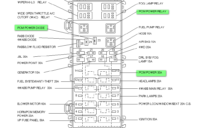
For the seasoned DIY mechanic or the enthusiastic Ford Ranger owner looking to delve deeper into their truck's electrical system, understanding the fuse box is paramount. This article provides a comprehensive guide to the fuse box diagram for a 2000 Ford Ranger. Think of it as your electrical roadmap, crucial for troubleshooting, repairs, and even safe modifications.
Purpose of the Fuse Box Diagram
Why bother with a fuse box diagram? Simple: it's indispensable for several reasons:
- Troubleshooting Electrical Issues: A blown fuse is often the culprit behind malfunctioning lights, accessories, or even starting problems. The diagram pinpoints the exact fuse responsible for a specific circuit, saving you time and preventing unnecessary replacements.
- Safe Modifications: Adding aftermarket accessories like lights, stereos, or auxiliary power sources requires tapping into the electrical system. The diagram helps you identify appropriate circuits and fuse ratings, preventing overloads and potential fires.
- Understanding Your Truck: Even without immediate problems, knowing your Ranger's electrical architecture empowers you to understand its inner workings and perform preventative maintenance.
Key Specs and Main Parts
A 2000 Ford Ranger typically has two fuse boxes:
- Under-Dash Fuse Box: Located on the driver's side, usually beneath the dashboard. This box houses fuses for interior components like lights, radio, wipers, and instrument cluster.
- Power Distribution Box (Under-Hood Fuse Box): Situated in the engine compartment, this box contains fuses and relays for high-current circuits such as the starter, alternator, fuel pump, and headlights.
Each fuse box contains:
- Fuses: These are sacrificial devices designed to protect circuits from overcurrent. They contain a thin metal filament that melts and breaks the circuit when the current exceeds its rating. Fuses are rated in Amperes (Amps or A), indicating the maximum current they can handle.
- Relays: Electrically operated switches that control high-current circuits using a low-current signal. Relays are essential for components like the starter motor and fuel pump, where the switch located inside the cab couldn't safely handle the full current draw.
- Circuit Breakers: Similar to fuses, but they can be reset after tripping. Circuit breakers are often used for circuits that experience intermittent overloads.
- Wiring Harness Connectors: Where the wiring bundles plug into the fuse box, distributing power to the respective circuits.
Symbols – Deciphering the Diagram
Understanding the symbols on a fuse box diagram is crucial. Here's a breakdown:
- Lines: Represent wires connecting components. The thickness may indicate the wire gauge (thicker wires handle more current).
- Colors: Wires are color-coded to help identify their function. The diagram will include a color code chart. Common colors include:
- Red: Typically indicates a power wire (connected to the battery).
- Black: Usually represents ground.
- Other Colors (e.g., Blue, Yellow, Green): Each color represents a specific circuit or function.
- Icons: Pictorial representations of the components protected by each fuse. Examples include:
- Light Bulb: Indicates a lighting circuit (headlights, taillights, etc.).
- Radio: Represents the audio system.
- Windshield Wiper: Signifies the wiper system.
- Engine: Could indicate engine management systems.
- Numerical Values: Indicate the fuse's amperage rating (e.g., 10A, 20A, 30A). It's *crucial* to replace a blown fuse with one of the same amperage rating.
The diagram will also typically include a table listing each fuse or relay, its amperage rating, and the components it protects. This table is your primary reference when troubleshooting.
How It Works – Electrical Circuit Basics
At its core, an electrical circuit is a closed loop that allows current to flow from a power source (the battery) through a component (like a headlight) and back to the power source. The fuse acts as a gatekeeper in this loop. If the current exceeds the fuse's rating, the fuse blows, interrupting the circuit and preventing damage to the component or wiring.
Relays, on the other hand, use a small current to control a larger current. When a switch (like your headlight switch) is activated, it sends a small current to the relay's coil. This coil energizes and closes the relay's contacts, allowing the high-current circuit to power the headlights. This prevents the switch from having to handle the high current directly, prolonging its life and improving safety.
Real-World Use – Basic Troubleshooting
Here's how to use the fuse box diagram for basic troubleshooting:
- Identify the Problem: Determine which component is malfunctioning (e.g., the radio isn't working).
- Consult the Diagram: Locate the fuse or relay associated with that component in the fuse box diagram.
- Inspect the Fuse: Visually inspect the fuse. A blown fuse will have a broken filament. You can also use a multimeter to test for continuity across the fuse.
- Replace the Fuse: If the fuse is blown, replace it with a new fuse of the same amperage rating.
- Test the Component: After replacing the fuse, test the component to see if it's working.
- If the Fuse Blows Again: If the new fuse immediately blows, there's likely a short circuit in the wiring or the component itself. Further investigation is required. This may involve checking wiring for damage or testing the component with a multimeter.
Safety – Proceed with Caution
Working with electrical systems can be dangerous. Here are some crucial safety precautions:
- Disconnect the Battery: Always disconnect the negative battery terminal before working on the electrical system. This prevents accidental shorts and electrical shocks.
- Use Proper Tools: Use insulated tools designed for electrical work.
- Never Replace a Fuse with a Higher Amperage Rating: This can overload the circuit and cause a fire.
- Be Careful Around the Power Distribution Box: This box contains high-current circuits that can deliver a dangerous shock. Avoid touching terminals or wires unnecessarily.
- Consult a Professional: If you're unsure about any aspect of electrical work, consult a qualified mechanic. Do not work on potentially dangerous electrical components such as the ABS module, airbags, or PCM without proper training. These systems can cause serious harm if mishandled.
Specifically, the power distribution box under the hood houses relays and fuses for critical systems like the fuel pump and ignition. Tampering with these circuits incorrectly could result in engine damage or even a vehicle fire.
Remember, the fuse box diagram is your guide, but common sense and safety precautions are essential when working on your 2000 Ford Ranger's electrical system.
We have a complete, downloadable PDF file of the 2000 Ford Ranger fuse box diagram. Please reach out through the contact information provided to request the diagram file. We hope this article has given you a solid foundation for understanding your vehicle's electrical system.