Fuse Box Diagram For A 2003 Ford Expedition
Whether you're tackling an electrical gremlin, adding a new accessory, or just trying to understand your vehicle better, a fuse box diagram is an invaluable tool. This article provides a deep dive into the fuse box diagram for a 2003 Ford Expedition, arming you with the knowledge to confidently navigate its electrical system.
Why You Need a Fuse Box Diagram
The fuse box diagram serves multiple crucial purposes:
- Troubleshooting Electrical Problems: When a component stops working (e.g., a headlight, the radio, a power window), the first step is usually to check the corresponding fuse. The diagram tells you exactly which fuse to inspect.
- Installing Aftermarket Accessories: Adding accessories like amplifiers, aftermarket lights, or remote starters requires tapping into the vehicle's electrical system. A fuse box diagram helps you identify suitable circuits for a clean and safe installation.
- Understanding Your Vehicle: Familiarizing yourself with the fuse layout gives you a better understanding of how different electrical components are interconnected and protected.
- Avoiding Costly Repairs: A blown fuse can often be diagnosed and replaced quickly and inexpensively at home, saving you a trip to the mechanic.
Key Specs and Main Parts of the Fuse Boxes
The 2003 Ford Expedition typically has two main fuse box locations:
- Engine Compartment Fuse Box: Located under the hood, this box houses fuses and relays that protect critical engine and powertrain components, lighting systems, and other high-current circuits.
- Interior Fuse Box: Usually located under the dashboard, often on the driver's side, this box contains fuses for interior components like the radio, power windows, climate control, and instrument panel.
Key Specifications vary depending on the specific Expedition trim level and options, but some common elements are:
- Fuse Types: Blade-type fuses (also known as spade fuses) are the most common. These come in various sizes, including mini, standard, and maxi.
- Fuse Ratings: Fuses are rated in amperes (amps or A). This indicates the maximum current the fuse can handle before it blows. Common ratings include 5A, 7.5A, 10A, 15A, 20A, 25A, 30A, and higher. Using a fuse with a higher amperage than specified can lead to serious electrical damage and even fire.
- Relays: Relays are electromechanical switches that control high-current circuits using a low-current signal. They're commonly used for components like headlights, fuel pumps, and starter motors.
Decoding the Symbols and Legends
A fuse box diagram uses symbols and abbreviations to represent different components and their functions. Understanding these symbols is crucial for interpreting the diagram correctly.
- Lines: Solid lines typically represent electrical wires connecting components. Dashed lines may indicate ground connections or control signals.
- Colors: Wire colors are often indicated on the diagram using abbreviations or color codes (e.g., RD for red, BLK for black, BLU for blue). Knowing the wire color can help you trace circuits and identify specific wires.
- Icons: Specific icons represent different components. Here are some common examples:
- Lightbulb: Headlights, taillights, interior lights
- Motor: Window motors, wiper motors
- Speaker: Radio and audio system
- Coil: Relays, solenoids
- Rectangular Box: Control modules (e.g., PCM, ABS module)
- Abbreviations: Common abbreviations include:
- PCM: Powertrain Control Module (engine computer)
- ABS: Anti-lock Braking System
- GEM: Generic Electronic Module
- RAP: Remote Anti-theft Personality
The diagram will also include a legend, which is a key that explains what each symbol, abbreviation, and color code represents. This is your go-to reference for deciphering the diagram.
How It Works: Fuse Protection
The fundamental principle behind a fuse is simple: it's a sacrificial device designed to protect an electrical circuit from overcurrent. Inside a fuse is a thin strip of metal. When the current flowing through the circuit exceeds the fuse's rated amperage, the metal strip heats up and melts, breaking the circuit and stopping the flow of electricity. This prevents damage to the wiring, components, and potentially the entire vehicle.
Fuses are connected in series with the component they protect. This means that all current flowing to the component must first pass through the fuse. If a short circuit occurs (e.g., a wire chafes against the chassis and creates a direct path to ground), a large amount of current will flow, quickly blowing the fuse.
Real-World Use: Basic Troubleshooting
Here's how to use the fuse box diagram for basic troubleshooting:
- Identify the Problem: Determine which component is malfunctioning (e.g., the radio isn't working).
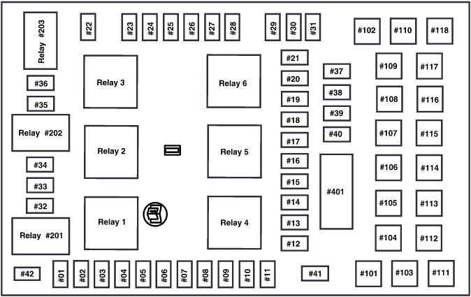
- Consult the Diagram: Locate the fuse box diagram (either in your owner's manual or a downloaded version). Find the fuse that corresponds to the malfunctioning component. The diagram will indicate the fuse location (e.g., fuse #22 in the interior fuse box) and its amperage rating.
- Inspect the Fuse: Using a fuse puller (or needle-nose pliers), carefully remove the fuse. Examine the metal strip inside. If the strip is broken or blackened, the fuse is blown and needs to be replaced.
- Replace the Fuse: Replace the blown fuse with a new fuse of the exact same amperage rating. Using a higher amperage fuse can bypass the circuit protection and lead to serious damage.
- Test the Component: Turn on the component to see if it now works. If the new fuse blows immediately, there's likely a short circuit in the wiring or the component itself. Further diagnosis is required.
Safety First: Handling Risky Components
Working with electrical systems involves inherent risks. Always take the following precautions:
- Disconnect the Battery: Before working on the fuse box or any electrical component, disconnect the negative terminal of the battery. This prevents accidental shorts and electrical shocks.
- Use Insulated Tools: Use tools with insulated handles to protect yourself from electric shock.
- Avoid Water: Never work on electrical systems in wet or damp conditions.
- High-Voltage Components: Be extremely cautious around high-voltage components like the ignition system. These can deliver a dangerous shock even with the battery disconnected.
- Airbags: Airbags are electrically activated. Incorrect handling can cause them to deploy unexpectedly, resulting in serious injury. If you need to work near airbag components, consult a professional.
Remember: If you're not comfortable working on electrical systems, it's always best to consult a qualified mechanic.
By understanding the fuse box diagram and taking appropriate safety precautions, you can confidently troubleshoot electrical problems, install accessories, and gain a deeper understanding of your 2003 Ford Expedition's electrical system.
We have a PDF file of the complete fuse box diagram for a 2003 Ford Expedition, feel free to download the diagram.