
Fuse Box Wiring Diagram For 1965 Vw Bug
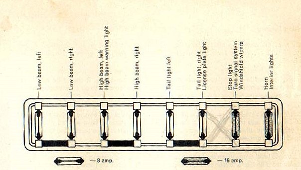
Let's dive into the wiring heart of your 1965 Volkswagen Beetle: the fuse box. This isn't just about replacing a blown fuse; understanding the fuse box wiring diagram is crucial for proper electrical repairs, modifications, and even just general troubleshooting. Having a clear grasp of this diagram empowers you to confidently diagnose and fix electrical issues in your beloved Bug. It's about taking control and knowing exactly what's going on under that vintage hood.
Why Bother with the Fuse Box Diagram?
A clear understanding of the fuse box wiring diagram is essential for a few key reasons:
- Troubleshooting: Electrical gremlins are common in older vehicles. The diagram lets you trace circuits, identify faulty components, and isolate the source of the problem.
- Repairs: When a circuit fails, knowing which fuse protects which component is vital. It prevents you from blindly replacing fuses or making incorrect connections.
- Modifications: Want to add a new radio, lights, or other accessories? The diagram helps you tap into the electrical system safely and correctly, ensuring you don't overload circuits.
- Restoration: During a full restoration, the wiring harness may need replacement or repair. The diagram is your roadmap to ensure everything is wired correctly to factory specifications.
- Education: Just learning how your car works. It is always a good thing.
Key Specs and Main Parts of the 1965 VW Beetle Fuse Box
The 1965 Beetle fuse box is a relatively simple affair compared to modern vehicles. Here's a breakdown of the key components:
- Fuse Box Housing: Typically made of bakelite or a similar early plastic, it holds the fuses and provides connection points for the wiring harness.
- Fuses: These are the sacrificial links in your electrical circuits. They're designed to blow and interrupt the circuit when excessive current flows, protecting more expensive components from damage. In 1965, VW Bugs primarily used ceramic bullet-style fuses.
- Terminals: These are the metal connectors within the fuse box where wires are attached, often using screw-down or spade connectors.
- Wiring Harness: This is the bundle of wires that connects the fuse box to the various electrical components throughout the vehicle.
Important Specs:
- Voltage: The entire system operates on 6 volts DC (Direct Current). This is critical to remember! Using 12-volt components or making incorrect voltage connections will damage your car.
- Fuse Ratings: Fuses are rated in Amperes (Amps), indicating the amount of current they can handle before blowing. The 1965 Beetle used various fuse ratings, typically ranging from 8 Amps to 25 Amps. Never replace a fuse with one of a higher amperage rating. This circumvents the protection mechanism and could cause a fire.
- Wire Gauge: The thickness of the wires (measured in gauge) is important. Thicker wires can carry more current. The diagram will help show the correct wire gauge for each circuit.
Decoding the Fuse Box Wiring Diagram
Understanding the symbols and conventions used in the wiring diagram is paramount. Here’s a breakdown:
Lines
Solid lines represent wires. The thickness of the line *doesn't* necessarily indicate wire gauge in all diagrams, so always refer to the legend or accompanying text.
Colors
Wire colors are essential for identifying circuits. Common colors in a '65 Beetle include:
- Red: Typically indicates a power source or "hot" wire connected directly to the battery (through the ignition switch in most cases).
- Brown: Almost universally used for ground wires (connected to the vehicle's chassis).
- Black: Often used for switched power or general wiring.
- Other Colors (Blue, Green, White, Yellow, etc.): These are used for various circuits, such as lighting, turn signals, and accessories. The diagram's legend will specify which circuits each color represents.
Icons
Symbols represent different components. Here are a few examples:
- A zig-zag line inside a circle is generally a fuse.
- A rectangle with a diagonal line through it could represent a relay or a resistor.
- A circle with a "T" inside is typically a terminal or connection point.
- Simplified images represent items like headlights, taillights, the ignition switch and other devices.
Reading the Diagram: Start at the power source (typically the battery, shown on the diagram). Trace the wires through the ignition switch, fuse box, and out to the various components. Pay close attention to the colors of the wires and the fuse ratings.
How It Works: A Simple Example
Let's take the headlight circuit as an example. The diagram will show a red wire (power) coming from the ignition switch to the fuse box. From there, a wire (perhaps blue or white) runs from the fuse to the headlight switch. When you turn on the headlight switch, power flows through the wire to the headlights, completing the circuit and illuminating them. If the fuse blows, it breaks this circuit, preventing the headlights from working.
Real-World Use: Basic Troubleshooting Tips
Here are some basic troubleshooting tips using the fuse box diagram:
- No Power to a Component: Check the fuse for that circuit. If it's blown, replace it with the correct amperage rating. If the new fuse blows immediately, there's a short circuit in the wiring or a faulty component on that circuit. Use the diagram to trace the wiring and look for damaged insulation or exposed wires touching the chassis.
- Intermittent Problems: Loose connections are common culprits. Inspect the terminals in the fuse box and at the component for corrosion or looseness. Clean and tighten them as needed.
- Dim Lights: Could be a bad ground. Check the ground wires (usually brown) connected to the chassis. Clean the connection points to ensure a good electrical path. Low voltage from the battery or a failing generator (dynamo) can also cause dim lights.
- Battery Drain: If your battery keeps dying, there could be a parasitic drain. The diagram can help you isolate which circuits are drawing power when the car is off. Disconnect circuits one by one (after removing the fuse) to see if you can isolate the cause.
Safety First!
Working with electrical systems can be dangerous. Here are some crucial safety precautions:
- Disconnect the Battery: Before working on any electrical component, always disconnect the negative (-) battery terminal. This prevents accidental shorts and potential shocks.
- Work in a Well-Lit Area: Good visibility is essential for identifying wires and connections accurately.
- Use Proper Tools: Use insulated tools designed for electrical work. Avoid using pliers or screwdrivers with damaged insulation.
- Don't Work When Wet: Water conducts electricity, increasing the risk of shock.
- High-Risk Components: The generator, starter motor, and ignition coil carry high voltages and currents. Exercise extreme caution when working around these components. The ignition coil can deliver a nasty shock even with the battery disconnected if it has residual charge.
- Double-Check Your Work: Before reconnecting the battery, carefully review your work to ensure all connections are correct and secure.
Remember, if you're uncomfortable working on electrical systems, it's always best to consult a qualified mechanic. Your safety and the integrity of your classic Beetle are paramount.
We have a high-resolution, printable PDF of the 1965 VW Beetle Fuse Box Wiring Diagram available for download. This diagram will be an invaluable resource for any electrical work you undertake on your Bug.