Fuse Panel 1989 Chevy 1500 Fuse Box Diagram
Alright, let's dive into the fuse panel diagram for a 1989 Chevy 1500. This isn't just some piece of paper; it's your lifeline when electrical gremlins start causing havoc. Whether you're chasing down a blown fuse, diagnosing a short, or even adding some aftermarket goodies, understanding this diagram is crucial. We're talking about the brains of your truck's electrical system, so buckle up!
Purpose: Your Electrical Troubleshooting Roadmap
Why bother with a fuse panel diagram? Simple: it's the key to diagnosing and repairing electrical problems. Imagine trying to find a specific wire in a massive harness without a map – that's what working on your '89 Chevy 1500's electrical system is like without a fuse panel diagram. This diagram provides:
- Identification: Quickly locate the fuse or circuit breaker protecting a specific component.
- Troubleshooting: Trace circuits to identify the source of a problem (e.g., a short circuit or open circuit).
- Modification: Determine appropriate circuits for tapping into when adding aftermarket accessories like lights, stereos, or alarms.
- Safety: Understand the amperage ratings of fuses to prevent overloads and potential fires.
Key Specs and Main Parts
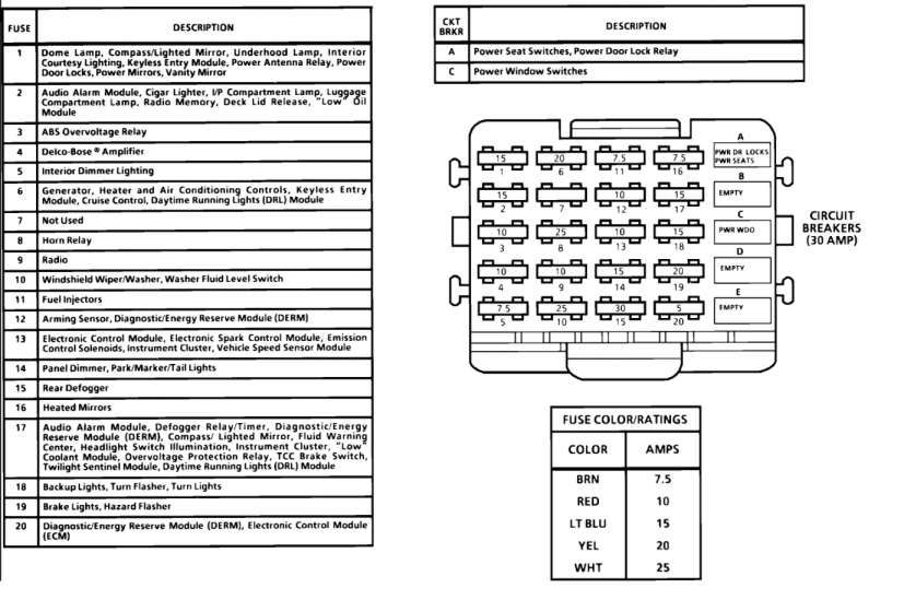
The fuse panel on a 1989 Chevy 1500 is typically located on the driver's side, either under the dashboard near the parking brake pedal or on the side of the dashboard, accessible when the driver's door is open. It houses several components:
- Fuses: These are sacrificial devices designed to protect circuits from overcurrent. When the current exceeds the fuse's rating, the fuse melts (opens the circuit), preventing damage to other components. Fuse types commonly found include blade fuses (ATO/ATC style) and sometimes, older glass tube fuses.
- Circuit Breakers: Similar to fuses, but they can be reset after tripping. They're typically used for high-current circuits like power windows or locks.
- Relays: Electrically operated switches that control high-current circuits with a low-current signal. Relays allow switches to control things like headlights, fuel pumps, and other power-hungry devices without running high current through the switch itself.
- Fuse Block/Panel: The physical housing that holds the fuses, circuit breakers, and relays. It provides connections for the wiring harness.
- Wiring Harness Connectors: These connectors plug into the fuse block and carry power and signals to and from the various circuits.
Key Specifications to Note:
- Voltage: The system operates at 12V DC (Direct Current).
- Amperage Ratings: Each fuse is rated for a specific amperage (e.g., 5A, 10A, 15A, 20A, 25A, 30A). Using a fuse with a higher amperage rating than specified can damage the circuit and create a fire hazard.
- Wire Gauge: The thickness of the wires in the circuits. Thicker wires can handle more current.
Symbols: Decoding the Diagram
Understanding the symbols on the fuse panel diagram is critical. Here's a breakdown of common symbols:
- Lines: Represent wires. Solid lines usually indicate power wires, while dashed lines might represent ground wires or control signals. The thickness of the line might (but not always) give you an idea of the wire gauge.
- Fuse Symbol: Usually a zig-zag line inside a rectangle or a simple rectangle. The amperage rating is often written next to the symbol.
- Circuit Breaker Symbol: Similar to a fuse symbol, but often with a small switch or lever depicted.
- Relay Symbol: Typically a coil symbol connected to a switch symbol. The coil represents the electromagnet that activates the switch.
- Ground Symbol: Looks like a series of descending horizontal lines, indicating a connection to the vehicle's chassis (ground).
- Connector Symbols: Represented by circles or squares with lines entering and exiting. These indicate where the wiring harness connects to the fuse block or other components.
- Color Codes: The diagram will often use color codes to identify wires. Common colors include red (power), black (ground), blue, yellow, green, brown, and white. A color code chart is essential. For example, a wire labeled "BLU/WHT" would be a blue wire with a white stripe.
Pay attention to the legend on the diagram. The legend will define all the symbols and abbreviations used. Without it, you will struggle to properly understand how to use the diagram.
How It Works: A Simplified Explanation
The fuse panel acts as a central distribution point for electrical power. Power from the battery flows to the fuse panel, and from there, it's distributed to various circuits throughout the vehicle. Each circuit is protected by a fuse or circuit breaker. When a component is turned on (e.g., headlights), current flows through the circuit. If there's a short circuit (e.g., a wire chafes against the chassis), the current flow increases dramatically. This high current causes the fuse to blow, interrupting the circuit and preventing further damage. Relays are used to switch high-current circuits on and off using a low-current control signal. This protects switches from being overloaded.
Real-World Use: Basic Troubleshooting Tips
Here's how you can use the fuse panel diagram for basic troubleshooting:
- Identify the Problem: Determine which component is not working (e.g., the radio, the headlights, the windshield wipers).
- Consult the Diagram: Locate the fuse or circuit breaker associated with that component on the fuse panel diagram.
- Inspect the Fuse: Remove the fuse and visually inspect it. If the filament is broken, the fuse is blown. A blown fuse is a sign of too much current flowing through the circuit, and this needs to be identified.
- Replace the Fuse: Replace the blown fuse with a new fuse of the exact same amperage rating. Never use a higher amperage fuse.
- Test the Component: Turn on the component to see if it now works.
- If the Fuse Blows Again: If the new fuse blows immediately or shortly after being replaced, there's likely a short circuit in the wiring or the component itself. Further diagnosis is required. This could involve checking for damaged wires, loose connections, or a faulty component. A multimeter is essential for this type of troubleshooting.
Safety: Proceed with Caution
Working with electrical systems can be dangerous. Here are some safety precautions:
- Disconnect the Battery: Always disconnect the negative battery cable before working on the electrical system to prevent accidental shorts and shocks.
- Use Proper Tools: Use insulated tools designed for automotive electrical work.
- Never Bypass a Fuse: Never bypass a fuse or circuit breaker by using a piece of wire or a higher amperage fuse. This can create a fire hazard.
- Be Aware of Airbag Systems: If you're working near the airbag system, be extremely cautious. Disconnecting the battery might not be enough to prevent accidental airbag deployment. Consult the service manual for specific instructions on disabling the airbag system.
- Capacitors in the ECM: Capacitors in the Electronic Control Module can hold a charge even with the battery disconnected. Wait a reasonable time after disconnecting the battery to allow them to discharge before handling the ECM.
The fuel pump circuit, headlight circuit, and ignition circuits carry high current and should be treated with particular respect.
Remember, if you're uncomfortable working on the electrical system, it's always best to consult a qualified mechanic. Electrical issues can be complex and potentially dangerous if not handled correctly.
To help you out even more, we have the full 1989 Chevy 1500 fuse panel diagram available for download. It's a valuable resource to keep handy when tackling any electrical work on your truck.