Fuse Panel 1996 Honda Civic Fuse Box Diagram
Alright, let's dive into the fuse panel diagram for your 1996 Honda Civic. Whether you're troubleshooting an electrical issue, planning a modification, or simply want a better understanding of your car's electrical system, having a solid grasp of this diagram is crucial. This article will break down the diagram, explaining its key components, symbols, and how to use it for practical troubleshooting. And the best part? We've got a downloadable version of the fuse box diagram ready for you – more on that later!
Why Understanding the Fuse Panel Diagram Matters
The fuse panel diagram is essentially a roadmap of your Civic's electrical system. It tells you which fuse protects which circuit, and what amperage that fuse is rated for. Without it, you're flying blind when faced with electrical problems. Here's why it's so important:
- Troubleshooting Electrical Issues: When a component stops working – a light, the radio, the power windows – the first thing you should check is the fuse. The diagram pinpoints the correct fuse quickly and efficiently.
- Planning Modifications: Adding aftermarket accessories like amplifiers, alarms, or lighting requires tapping into the electrical system. The diagram shows you where you can safely draw power and what size fuse to use for the added circuit.
- Understanding Your Car: Knowing how the electrical system is laid out gives you a deeper understanding of how your car works overall.
- Avoiding Costly Repairs: Diagnosing and fixing simple electrical problems yourself can save you a significant amount of money on mechanic bills.
Key Specs and Main Parts of the 1996 Honda Civic Fuse Panel
The 1996 Honda Civic has two main fuse boxes: the under-dash fuse box (located inside the cabin, usually on the driver's side, near the steering column) and the under-hood fuse box (located in the engine compartment). Each box contains a series of fuses and relays protecting various circuits.
Here's a breakdown of the key parts:
- Fuses: These are sacrificial devices designed to protect electrical circuits from overcurrent. They contain a thin wire that melts and breaks the circuit if the current exceeds its rated amperage.
- Relays: Relays are electromechanical switches that allow a low-current circuit to control a high-current circuit. They're used to control things like headlights, the fuel pump, and the starter motor.
- Fuse Panel Housing: This is the physical enclosure that holds the fuses and relays.
- Fuse Puller: A small plastic tool (often found inside the fuse box) used to safely remove fuses.
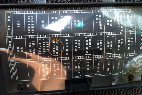
- Fuse Diagram (Label): The diagram is usually printed on the inside of the fuse box cover or on a separate label attached nearby. This is what we're focusing on in this article.
The amperage rating of each fuse is crucial. Using a fuse with a higher amperage than specified can allow excessive current to flow, potentially damaging components or even causing a fire. Always replace a blown fuse with one of the same amperage rating.
Decoding the Symbols: Lines, Colors, and Icons
The fuse panel diagram uses a system of symbols to represent different components and circuits. Understanding these symbols is essential for interpreting the diagram correctly.
- Lines: Lines represent electrical wires or circuits. Thicker lines may indicate higher current-carrying capacity.
- Colors: Different colored wires often represent different functions or voltage levels. The diagram might not always explicitly state the color of each wire, but often a color legend is included. Common colors are red (power), black (ground), and various other colors for signal or control wires.
- Icons: Icons represent the components protected by each fuse. These can include:
- Light Bulb: Indicates a lighting circuit (headlights, taillights, interior lights).
- Radio: Indicates the radio or audio system circuit.
- Fan: Indicates a cooling fan circuit (radiator fan, A/C fan).
- Engine Symbol: Indicates an engine management circuit (fuel pump, injectors, sensors).
- Window: Indicates a power window circuit.
- Horn: Indicates the horn circuit.
- Numbers: Numbers typically indicate the amperage rating of the fuse (e.g., 10A, 15A, 20A).
The diagram will also often include abbreviations to describe the circuit being protected. For example: "IGN" for ignition, "ACC" for accessory, "HTR" for heater, etc.
How It Works: From Fuse to Component
The fuse panel diagram shows the path of electricity from the battery, through the fuse, and to the component it protects. Let's consider a simplified example: the radio.
- The battery provides power to the electrical system.
- A wire carries power from the battery to the fuse box.
- The diagram identifies a specific fuse (e.g., 10A) that protects the radio circuit.
- Power flows through that fuse. If the fuse is intact, the power continues.
- The wire connects to radio.
- If the radio attempts to draw more current than the fuse's rating (10A in this case), the fuse will blow, breaking the circuit and preventing damage to the radio.
This same principle applies to all the circuits protected by fuses in the fuse panel. The diagram acts as a guide to trace the flow of electricity and identify potential points of failure.
Real-World Use: Basic Troubleshooting Tips
Here's how you can use the fuse panel diagram for basic troubleshooting:
- Identify the Problem: Determine which component is not working (e.g., the cigarette lighter, the windshield wipers).
- Consult the Diagram: Locate the fuse that protects that component on the diagram. Note the fuse's amperage rating and location in the fuse box.
- Inspect the Fuse: Use the fuse puller to remove the fuse. Visually inspect it. A blown fuse will typically have a broken wire or a dark, burned spot inside the glass or plastic housing.
- Test the Fuse (Optional): For a more definitive test, use a multimeter in continuity mode. If the fuse is good, the multimeter will beep or show a reading of close to 0 ohms. If the fuse is blown, the multimeter will show no continuity (an open circuit).
- Replace the Fuse: If the fuse is blown, replace it with a new fuse of the same amperage rating.
- Test the Component: Turn on the component to see if it now works.
- If the Fuse Blows Again: If the new fuse blows immediately, there's likely a short circuit or overload in the circuit. This requires further investigation and might be best left to a professional mechanic.
Safety First: Highlighting Risky Components
Working with electrical systems can be dangerous if you're not careful. Here are some key safety precautions:
- Disconnect the Battery: Before working on any electrical components, disconnect the negative (-) terminal of the battery to prevent accidental shocks or short circuits.
- Use Insulated Tools: Use tools with insulated handles to protect yourself from electric shock.
- Don't Exceed Fuse Ratings: Never replace a fuse with one of a higher amperage rating. This can overload the circuit and cause a fire.
- Be Aware of High-Voltage Components: Components like the ignition coil and the charging system (alternator) can carry high voltages. Avoid touching these components while the engine is running.
- Work in a Well-Lit Area: Good visibility is essential for safe and accurate work.
Disclaimer: Working on automotive electrical systems involves inherent risks. If you're not comfortable working with electricity, it's best to consult a qualified mechanic.
So there you have it – a comprehensive guide to understanding the 1996 Honda Civic fuse panel diagram. Remember to always prioritize safety and consult the diagram before making any changes to your car's electrical system.
And as promised, we have the complete 1996 Honda Civic fuse box diagram available for you to download. With this resource at your fingertips, you'll be well-equipped to tackle any electrical troubleshooting or modification project on your Civic. Happy wrenching!