Fuse Panel 2000 Ford Mustang V6 Fuse Diagram
Alright, let's dive into the fuse panel diagram for your 2000 Ford Mustang V6. Understanding this layout is crucial whether you're diagnosing a blown fuse, adding aftermarket accessories, or just wanting to know your car's electrical system a bit better. This guide will break down the fuse panel's components, how it works, and how to use the diagram effectively for troubleshooting. We'll assume you're familiar with basic automotive tools and safety procedures, but we'll still highlight important precautions.
Purpose of the Fuse Panel Diagram
Why is a fuse diagram so important? Simply put, it's your roadmap to the electrical nervous system of your Mustang. Without it, troubleshooting electrical problems becomes a frustrating guessing game. With it, you can quickly identify the fuse responsible for a specific circuit, like your headlights, power windows, or fuel pump. This diagram is invaluable for:
- Troubleshooting Electrical Problems: Pinpointing and replacing blown fuses instead of blindly replacing components.
- Adding Aftermarket Accessories: Safely tapping into existing circuits for new lights, stereos, or other modifications.
- Understanding Vehicle Systems: Gaining a deeper understanding of how your car's electrical systems are interconnected.
- Preventative Maintenance: Periodically checking fuse conditions to prevent larger electrical failures.
Key Specs and Main Parts
The 2000 Mustang V6 primarily has two main fuse locations: one located inside the passenger compartment, usually under the dashboard near the driver's side, and another in the engine compartment. This guide focuses on both. While specific amperage ratings might vary slightly depending on your car's options (e.g., Mach 460 sound system), the general layout and function remain consistent.
Passenger Compartment Fuse Panel
This panel typically houses fuses for interior components. Key components include:
- Fuse Block: The plastic housing that holds the fuses.
- Fuses: The protective devices that break the circuit when overloaded. They come in various amperage ratings (e.g., 5A, 10A, 15A, 20A, 30A).
- Relays: Electromechanical switches that control higher-current circuits, often triggered by lower-current signals. While not technically fuses, relays are crucial components and are often indicated in the fuse diagram.
- Fuse Puller: A small plastic tool used to safely remove fuses without damaging them or the panel.
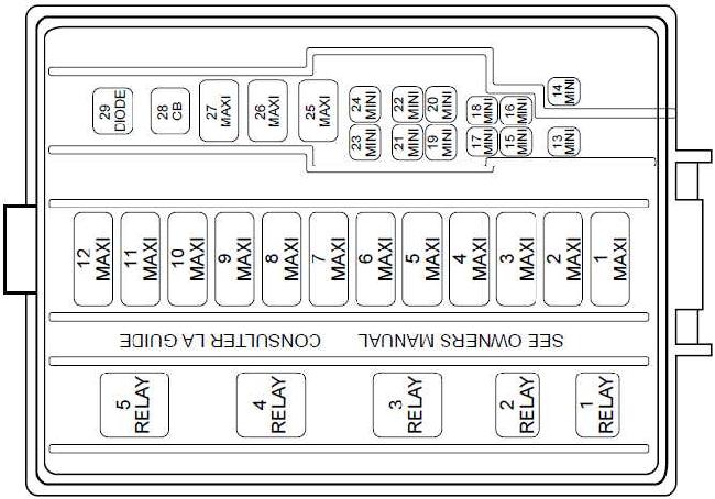
Engine Compartment Fuse Panel (Power Distribution Box)
This panel handles higher-current circuits and is usually located near the battery. Key components include:
- Fuse Block: Similar to the interior panel, but often larger and more robust.
- Fuses: Usually larger blade-type fuses and sometimes cartridge fuses to handle higher amperage.
- Relays: Controls high-current systems such as the starter motor, fuel pump, and cooling fan.
- Mega-Fuses/Maxi-Fuses: Very high-amperage fuses that protect major circuits like the alternator and main power feeds.
Symbols – Understanding the Fuse Diagram
The fuse diagram isn't just a pretty picture; it's a language. Understanding the symbols is key to using it effectively. Here's a breakdown:
- Lines: Solid lines represent the electrical circuits. Thicker lines may indicate higher-current circuits.
- Boxes: Represent fuses. Numbers inside or adjacent to the box indicate the fuse's amperage rating (e.g., "20" means 20 amps).
- Circles/Squares with Letters: Represent relays. The letters (e.g., "FP" for Fuel Pump Relay) indicate the relay's function.
- Color Coding: While not always present on all diagrams, some may use color coding to distinguish between different types of circuits (e.g., red for power, black for ground).
- Icons: Small icons next to the fuse designation indicate the component or system the fuse protects (e.g., a headlight icon for the headlight fuse). These are often universal symbols but can vary slightly.
- Ground Symbols: The chassis ground symbol (typically a series of decreasing horizontal lines) indicates where the circuit connects to the car's body for grounding.
The diagram typically includes a legend or key that explains all the symbols used. Always refer to the legend first if you're unsure about a particular symbol.
How It Works: The Fuse's Function
The fuse is a sacrificial device designed to protect the electrical circuit. It contains a thin wire or strip of metal that melts and breaks the circuit when the current exceeds a specified level. This prevents damage to more expensive components, such as the wiring harness, control modules, and accessories. Think of it like a circuit breaker in your home's electrical panel, but on a smaller scale.
When a fuse blows, it's usually a symptom of an underlying problem. The overload could be caused by:
- Short Circuit: A direct connection between a hot wire and ground, resulting in a massive current flow.
- Overload: Too many devices drawing power from the same circuit.
- Component Failure: A faulty component drawing excessive current (e.g., a failing motor).
Real-World Use – Basic Troubleshooting Tips
Okay, let's get practical. Here's how to use the fuse diagram to troubleshoot common electrical problems:
- Identify the Problem: What's not working? (e.g., headlights, radio, power windows)
- Consult the Fuse Diagram: Locate the fuse or relay associated with the affected component or system in either the passenger compartment or engine compartment fuse box diagrams.
- Inspect the Fuse: Remove the fuse using the fuse puller. Examine the wire inside the fuse. If it's broken or blackened, the fuse is blown.
- Replace the Fuse: Replace the blown fuse with a new fuse of the exact same amperage rating. Using a higher amperage fuse can be extremely dangerous and cause a fire.
- Test the System: Turn on the affected component or system to see if the problem is resolved.
- If the Fuse Blows Again: This indicates an underlying problem that needs further investigation. Don't keep replacing the fuse – you'll likely cause more damage. Consult a qualified mechanic to diagnose the cause of the overload.
Example: Your power windows stopped working. You consult the fuse diagram and find that fuse #22 (20A) in the passenger compartment panel controls the power windows. You remove the fuse and see that the wire is broken. You replace it with a new 20A fuse, and the power windows now work. Problem solved!
Safety – Handle with Care!
Working with electrical systems can be dangerous. Always observe the following safety precautions:
- Disconnect the Battery: Whenever possible, disconnect the negative battery terminal before working on the electrical system to prevent accidental shorts.
- Use Proper Tools: Use insulated tools designed for automotive electrical work.
- Never Bypass a Fuse: Never replace a fuse with a piece of wire or a higher amperage fuse. This bypasses the safety protection and can cause a fire.
- Be Careful Around the Battery: Batteries contain sulfuric acid, which can cause burns. Avoid contact with skin and eyes.
- High-Voltage Components: Be extremely cautious around components like the ignition system (spark plugs, ignition coil) and the airbag system. These can carry high voltages and should only be handled by qualified technicians. It is highly recommended to disconnect the battery and wait at least 30 minutes before working on the airbag system to allow capacitors to discharge.
- Be Mindful of Capacitors: Some modules contain capacitors that can store a charge even after the battery is disconnected.
The engine compartment fuse panel contains fuses and relays that control critical systems like the fuel pump and starter motor. Be especially careful when working in this area, as tampering with these circuits can disable your car or create a fire hazard. Always double-check the diagram before making any changes.
Remember, if you're not comfortable working on electrical systems, it's always best to consult a qualified mechanic. Electrical problems can be complex, and improper repairs can lead to serious damage or injury.
Now that you understand the fuse panel diagram, you're well-equipped to tackle basic electrical troubleshooting on your 2000 Ford Mustang V6. We have the detailed fuse panel diagrams readily available in PDF format. They cover both the interior and engine bay fuse boxes, complete with amperage ratings and component assignments. Feel free to download it.