Fuse Panel 2000 Lincoln Town Car Fuse Box Diagram
Let's dive into the fuse panel diagram for your 2000 Lincoln Town Car. This isn't just some piece of paper; it's your roadmap to understanding, diagnosing, and potentially fixing electrical gremlins in your classic luxury vehicle. We'll cover everything from the basics to some advanced troubleshooting, ensuring you're well-equipped to tackle electrical issues with confidence. We have a downloadable file available for you containing the complete diagram - more on that later.
Purpose: Why This Diagram Matters
A fuse panel diagram is crucial for several reasons. Primarily, it's essential for electrical repairs. When a component stops working – say, your power windows, interior lights, or even the engine – the first thing you should check is the fuse. The diagram tells you exactly which fuse corresponds to that circuit. Furthermore, understanding the fuse layout is invaluable for any kind of electrical modification or upgrade. Adding a new audio system, installing aftermarket lights, or any other electrical enhancement requires knowledge of the existing circuits to avoid overloading them and causing damage.
Beyond repairs and modifications, studying the diagram gives you a deeper understanding of your car's electrical system. It helps you trace circuits, understand how different components are interconnected, and ultimately become a more knowledgeable and capable car owner. For a classic like the 2000 Town Car, preserving its electrical integrity is key to its longevity.
Key Specs and Main Parts
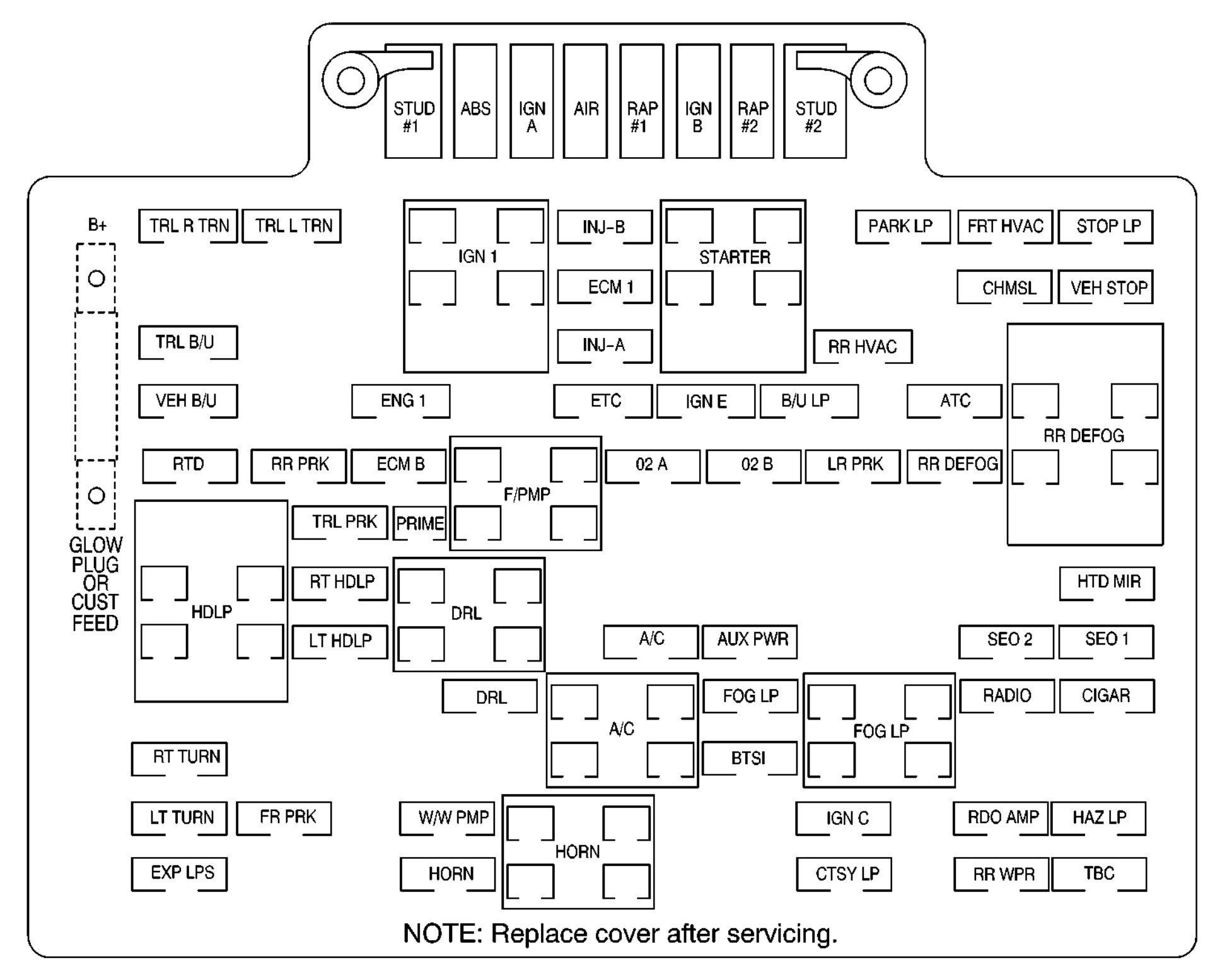
The 2000 Lincoln Town Car typically has two main fuse locations: the instrument panel fuse box (often located under the dashboard on the driver's side) and the power distribution box (located in the engine compartment, usually near the battery). Each location houses different fuses and relays responsible for various circuits. The specific amperage rating and function of each fuse are clearly indicated on the diagram. Relays, being electromechanical switches, control higher-current circuits, often for things like the starter motor, fuel pump, or cooling fan.
The diagram will also show the physical location of each fuse and relay within the box. This is crucial because even if you know the fuse number, finding its exact position without the diagram can be a time-consuming and frustrating process. You'll also find references to ground locations, which are critical for completing electrical circuits. A bad ground can mimic a blown fuse or other more serious problems.
Key components you’ll see listed on the diagram include:
- Fuses: These are sacrificial devices that protect circuits from overcurrent. They come in various amperage ratings (e.g., 5A, 10A, 20A, 30A).
- Relays: Electromechanical switches that control high-current circuits.
- Circuit Breakers: Resettable protection devices; less common than fuses but sometimes used for specific high-draw circuits.
- Grounds: Points where circuits are connected to the vehicle's chassis, providing a return path for current.
Symbols: Understanding Lines, Colors, and Icons
Fuse panel diagrams aren't just random lines and numbers; they use a standardized set of symbols to represent different components and their connections. Here's a breakdown of some common symbols you'll encounter:
- Solid Lines: Represent wires carrying current. Thicker lines often indicate wires carrying higher current.
- Dashed Lines: May represent control signals or communication lines rather than direct power feeds.
- Colors: Wires are color-coded to help identify them within the wiring harness. The diagram will have a legend that explains the color codes (e.g., Red = Power, Black = Ground).
- Fuse Symbol: A zigzag line within a rectangle typically represents a fuse.
- Relay Symbol: A square with a coil and a switch mechanism represents a relay.
- Ground Symbol: A series of downward-pointing lines, often resembling an inverted pyramid, indicates a ground connection.
Pay close attention to the legend on the diagram. It provides the key to understanding the symbols and color codes used throughout. Without the legend, interpreting the diagram is nearly impossible. Also, be aware that some aftermarket wiring diagrams may use slightly different symbols, so always refer to the specific legend provided with that diagram.
How It Works: Tracing a Circuit
The diagram allows you to trace the path of electricity from the power source (battery) through various components and back to ground. This is crucial for troubleshooting electrical problems. Let's say your cigarette lighter isn't working. The diagram will tell you which fuse protects the cigarette lighter circuit. If the fuse is blown, replacing it might solve the problem. However, if the fuse blows repeatedly, it indicates a short circuit somewhere in the system. Using the diagram, you can trace the wiring from the fuse to the cigarette lighter socket, looking for any damaged or frayed wires that might be causing the short.
Tracing a circuit involves understanding the series and parallel connections. Components connected in series share the same current, while components connected in parallel share the same voltage. Knowing how components are connected helps you isolate the source of a problem. For example, if several lights on the same circuit are not working, the issue is likely in the common part of the circuit (e.g., the fuse, the wiring to the first light in the series) rather than in each individual light.
Real-World Use: Basic Troubleshooting Tips
Here are some practical troubleshooting tips using the fuse panel diagram:
- Visual Inspection: Before checking fuses, visually inspect the fuse boxes for any signs of damage, corrosion, or water intrusion.
- Fuse Testing: Use a multimeter to test fuses for continuity. A blown fuse will have no continuity (infinite resistance). You can also use a fuse tester, which is a simpler tool that lights up if the fuse is good.
- Relay Testing: Relays can be tested using a multimeter to check the coil resistance and the continuity of the switch contacts. You can also often hear or feel the relay clicking when it's energized.
- Voltage Drops: Use a multimeter to measure voltage drops across various points in the circuit. Excessive voltage drops indicate resistance, which could be caused by corroded connections or damaged wiring.
- Short-to-Ground Testing: Use a multimeter to check for shorts to ground. Disconnect the negative battery terminal and measure the resistance between the circuit wire and ground. A low resistance reading indicates a short.
Example: Your power windows aren't working. Consult the diagram to identify the fuse for the power windows. Check the fuse. If it's blown, replace it with a fuse of the same amperage. If the new fuse blows immediately, there's likely a short circuit in the power window motor, wiring harness, or switch. Use the diagram to trace the wiring and look for any obvious signs of damage. If you can't find the short yourself, you might need to take it to a professional.
Safety: Highlight Risky Components
Working with electrical systems can be dangerous, so always follow these safety precautions:
- Disconnect the Battery: Always disconnect the negative battery terminal before working on the electrical system. This prevents accidental shorts and electrocution.
- Use Proper Tools: Use insulated tools designed for electrical work.
- Never Replace a Fuse with a Higher Amperage: This can overload the circuit and cause a fire. Always use a fuse with the correct amperage rating.
- Be Careful Around Airbags: Airbags are explosive devices, and accidentally triggering them can cause serious injury. Consult the vehicle's service manual for instructions on disabling the airbag system before working near it. Generally this involves disconnecting the battery and waiting a prescribed amount of time for the system to discharge.
- Capacitors: Be aware of capacitors, particularly in the audio system. These can store a charge even after the battery is disconnected and can deliver a shock.
Remember, certain components, such as the starter motor and alternator, carry very high currents. Exercise extreme caution when working around these components. Also, be mindful of the fuel system. Avoid creating sparks near fuel lines or fuel tanks, as this could ignite fuel vapors.
Working on your car's electrical system can be rewarding, but it's essential to prioritize safety. If you're not comfortable working with electricity, or if you encounter a complex problem, it's always best to consult a qualified mechanic.
As mentioned earlier, we have the complete fuse panel diagram for your 2000 Lincoln Town Car available for download. This detailed document will provide you with all the information you need to confidently troubleshoot and repair your vehicle's electrical system. Please look for the download link in the description below! It will be a huge help.