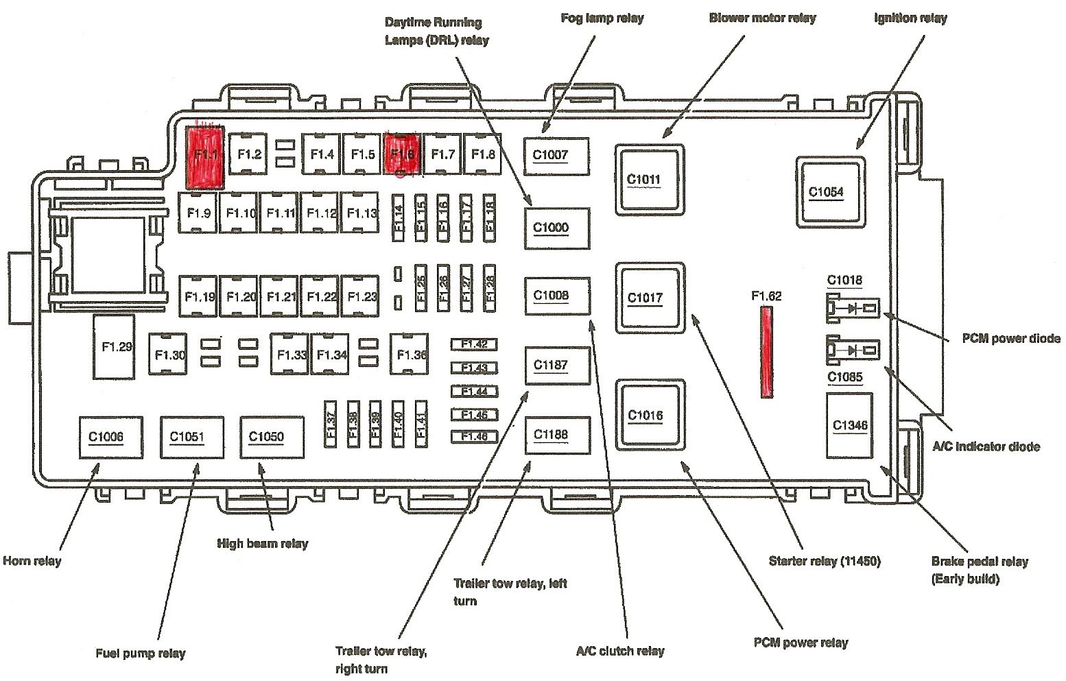
Fuse Panel 2004 Ford Explorer Fuse Box Diagram
The fuse panel diagram for your 2004 Ford Explorer is an invaluable resource for anyone who wants to understand, maintain, or modify their vehicle's electrical system. Whether you're troubleshooting a faulty circuit, adding aftermarket accessories, or simply trying to understand how different components are protected, having a clear fuse box diagram is essential. This guide provides a detailed breakdown of the 2004 Ford Explorer fuse panel, helping you navigate its complexities with confidence.
Why the Fuse Diagram Matters
A fuse box diagram isn't just a pretty picture; it's your roadmap to understanding your Explorer's electrical system. Its importance stems from several key areas:
- Troubleshooting Electrical Problems: When a specific electrical component fails (e.g., a taillight, the radio, or the windshield wipers), the fuse panel diagram is the first place to start. It helps you quickly identify the fuse associated with that component and check its condition.
- Safe Accessory Installation: Adding aftermarket accessories like lights, sound systems, or power inverters requires tapping into the vehicle's electrical system. The diagram helps you determine the appropriate fuse to tap into, ensuring you don't overload a circuit.
- Understanding Circuit Protection: The diagram reveals how the electrical system is organized and protected. Knowing which circuits are interconnected can prevent cascading failures and potentially damaging shorts.
- Performing Repairs: Sometimes, repairs involve replacing fuses or identifying the cause of a blown fuse. The diagram guides you through this process, minimizing the risk of making mistakes.
Key Specs and Main Parts
The 2004 Ford Explorer typically has two main fuse panel locations:
- Interior Fuse Panel: Usually located under the dashboard on the driver's side, or sometimes on the passenger side, this panel houses fuses protecting circuits for interior components such as the radio, lights, windows, and instrument panel.
- Engine Compartment Fuse Box (Power Distribution Box): Situated under the hood, usually near the battery, this box contains fuses and relays that protect and control critical engine and vehicle systems like the fuel pump, ignition system, anti-lock brakes (ABS), and exterior lighting.
Key components you'll find in both fuse boxes include:
- Fuses: The most fundamental protection devices. They are designed to break the circuit if the current exceeds a specified limit, preventing damage to wiring and components. They come in various amperages (measured in Amps or A), like 5A, 10A, 15A, 20A, 25A, and 30A.
- Relays: Electrically operated switches that control high-current circuits with a low-current signal. Relays are used for components that require significant power, such as the starter motor, headlights, and air conditioning compressor.
- Circuit Breakers: Similar to fuses, but resettable. They trip (open the circuit) when overloaded, but can be reset once the overload is removed. Some circuits may use circuit breakers instead of fuses, especially for components that experience intermittent high current draws.
- Fuse Puller: A small plastic tool used to safely remove fuses from the panel. This tool usually comes with the car, and many fuse boxes have a designated spot to clip it on.
Symbols: Decoding the Diagram
Understanding the symbols used in the fuse panel diagram is crucial for proper interpretation. While the specific symbols might vary slightly depending on the diagram's source, here are some common elements:
- Lines: Represent wires connecting components. Thicker lines may indicate higher current-carrying capacity.
- Fuse Symbols: Typically a squiggly line within a rectangle or circle. The amperage rating is usually indicated next to the symbol (e.g., 15A).
- Relay Symbols: Often depicted as a coil with a switch. The coil represents the relay's electromagnet, and the switch represents the contacts that open or close the circuit.
- Component Symbols: Represent various electrical components, such as headlights (circle with an X), horns (bell shape), motors (circle with an M), and sensors.
- Color Coding: Some diagrams use color-coded wires to represent different functions (e.g., red for power, black for ground).
- Ground Symbol: Usually three lines, decreasing in size, pointing downward, indicating the grounding point for the circuit.
Pay close attention to the legend or key provided with the diagram. It will define the specific symbols and abbreviations used in that particular diagram.
How It Works
The fuse box acts as a central distribution and protection point for the vehicle's electrical system. Power flows from the battery, through the main power distribution box, and then branches out to various circuits. Each circuit is protected by a fuse of the appropriate amperage. If a short circuit or overload occurs in a particular circuit, the fuse blows, interrupting the current flow and preventing damage to the wiring and components. Relays are used to switch high-current circuits on and off using low-current control signals, usually from a switch or a computer module.
Think of it like your home's electrical panel. Each fuse or circuit breaker protects a specific branch of the system. If you overload a circuit by plugging in too many devices, the breaker trips (or the fuse blows), cutting off power to that circuit to prevent a fire.
Real-World Use: Basic Troubleshooting Tips
Here's how to use the fuse panel diagram to troubleshoot common electrical problems:
- Identify the Problem: Determine which component is not working. For example, "the left taillight is out."
- Consult the Diagram: Locate the fuse associated with the left taillight in the appropriate fuse panel diagram (interior or engine compartment). The diagram will usually label the fuse as "Left Tail Lamp" or a similar description.
- Check the Fuse: Use a fuse puller to remove the fuse and inspect it. A blown fuse will have a broken filament (the thin wire inside the fuse). You can also use a multimeter set to continuity mode to test the fuse. A good fuse will show continuity (a beep or a reading of 0 ohms), while a blown fuse will show no continuity (no beep or an infinite resistance).
- Replace the Fuse: Replace the blown fuse with a new fuse of the exact same amperage. Never use a fuse with a higher amperage rating, as this can overload the circuit and cause damage.
- Test the Component: After replacing the fuse, test the component to see if it is working. If the fuse blows again immediately, there is likely a short circuit or other problem in the wiring or the component itself.
If a fuse keeps blowing, it indicates a problem beyond a simple overload. Seek professional assistance to diagnose and repair the underlying issue. Don't simply keep replacing fuses without finding the root cause.
Safety First
Working with your vehicle's electrical system can be dangerous if proper precautions are not taken.
- Disconnect the Battery: Before working on any electrical components, disconnect the negative battery terminal to prevent accidental short circuits and electrical shock.
- Use Insulated Tools: Use tools with insulated handles to avoid electrical shock.
- Never Exceed Fuse Ratings: Always replace a blown fuse with a fuse of the same amperage rating. Using a higher amperage fuse can overload the circuit and cause a fire.
- Be Careful Around the Airbag System: The airbag system is a sensitive electrical system. Avoid working on or near the airbag control module without proper training and precautions. Accidental deployment of an airbag can cause serious injury.
- High-Current Components: Be especially cautious around components like the starter motor, alternator, and battery. These components carry high currents and can cause severe burns or electrical shock if handled improperly.
Understanding the 2004 Ford Explorer fuse panel diagram empowers you to safely and effectively troubleshoot and maintain your vehicle's electrical system. Remember to prioritize safety and consult a qualified mechanic if you are unsure about any procedure.
We have a downloadable PDF file of the 2004 Ford Explorer fuse panel diagram available for your convenience. This file provides a clear and detailed reference that you can use in your garage or on the go.