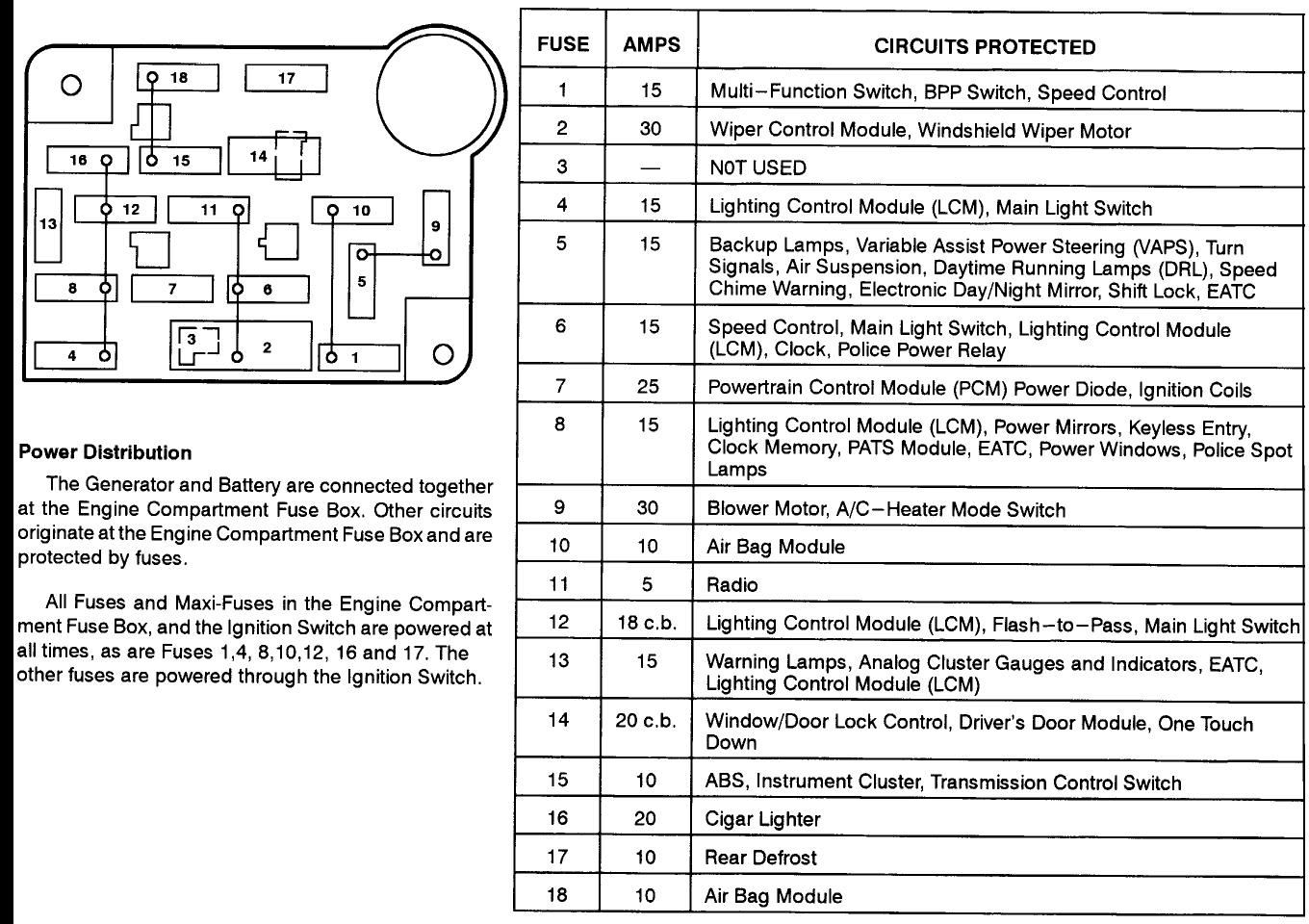
Fuse Panel 2004 Grand Marquis Fuse Box Diagram
Alright, let's dive into the fuse panel diagram for a 2004 Grand Marquis. Understanding this layout is crucial for anything from basic repairs to more involved modifications. Whether you're troubleshooting a blown fuse, adding aftermarket accessories, or just trying to get a better grasp of your car's electrical system, this diagram is your roadmap.
Purpose and Importance
Why bother with a fuse panel diagram? Simple: it's your first line of defense against electrical gremlins. It allows you to quickly identify and replace faulty fuses, potentially saving you time, money, and a trip to the mechanic. Beyond simple fixes, it empowers you to understand how various components of your car's electrical system are interconnected. This knowledge is invaluable when diagnosing more complex electrical issues or planning modifications. Think of it as an X-ray for your car's nervous system.
Having the diagram also helps prevent misdiagnosis. Substituting the wrong fuse size could lead to more serious damage or even a fire. Plus, some circuits control multiple systems; knowing this can streamline your troubleshooting process.
Key Specs and Main Parts of the Fuse Panel
The 2004 Grand Marquis typically has two main fuse panel locations: one inside the cabin, usually located under the dashboard on the driver's side, and another under the hood, often near the battery. We'll focus primarily on the interior fuse panel diagram as it's where many common accessory circuits are located.
Here's a breakdown of key components and terminology you'll encounter:
- Fuse Block/Panel: The physical housing where the fuses and relays are mounted.
- Fuses: Overcurrent protection devices. They contain a thin wire that melts and breaks the circuit when the current exceeds a specified level, preventing damage to components. They are rated in amperes (amps), often denoted by "A".
- Relays: Electromagnetic switches that use a small current to control a larger current. They are used to switch on/off circuits for high-power devices like headlights, fuel pumps, and air conditioning compressors.
- Circuit Breakers: Similar to fuses, but resettable. They trip (open the circuit) when overloaded and can be manually reset after the overload is removed. While less common in this era Grand Marquis for general circuits, they may protect specific components.
- Ground Points: Locations where electrical circuits are connected to the vehicle's chassis, providing a common return path for current.
Understanding the Fuse Panel Diagram Symbols
A fuse panel diagram is essentially a schematic drawing of the electrical circuits. Here's a guide to deciphering the common symbols you'll encounter:
- Lines: Represent wires or electrical conductors. Thicker lines might indicate heavier gauge wires carrying more current.
- Colors: Wires are often color-coded to help trace circuits. The diagram will usually include a color legend. Common colors include Red (often power), Black (ground), and various other colors for signals and control circuits. For example, a light green wire with a red stripe might indicate a specific signal wire for the audio system.
- Fuse Symbols: Typically shown as a zig-zag line within a rectangle. The number next to the symbol indicates the fuse amperage rating (e.g., "20A" means a 20-amp fuse).
- Relay Symbols: Represented as a coil symbol and a switch symbol. The coil represents the electromagnet that activates the switch.
- Component Symbols: Symbols for specific devices like headlights, radio, power windows, etc. These symbols are usually simplified representations of the actual component.
- Abbreviations: Abbreviations like "IGN" (ignition), "ACC" (accessory), "BAT" (battery) are frequently used to denote the power source or the function of the circuit.
Understanding the diagram requires recognizing the relationship between these symbols. The diagram shows you *where* each fuse protects *which* circuit and what amperage the fuse *must* be.
How It Works: The Electrical Flow
The fuse panel acts as a central distribution point for electrical power throughout your car. Power from the battery flows through the ignition switch and other control circuits to the fuse panel. From there, fuses protect individual circuits that supply power to various components. If a component draws too much current (e.g., due to a short circuit), the fuse for that circuit blows, interrupting the power flow and preventing damage. The diagram will trace from the power source, through the fuse, and finally to the component itself, allowing you to understand the path of current. Knowing the current path makes diagnosing problems exponentially easier.
Relays are used when a circuit requires a large amount of current that the switch itself cannot handle directly. For instance, the headlight switch doesn't directly power the headlights; it activates a relay that then supplies power to the headlights from the battery through a heavy-gauge wire and a dedicated fuse. This arrangement protects the switch from overload.
Real-World Use: Basic Troubleshooting
Here's how you can use the fuse panel diagram for basic troubleshooting:
- Identify the Problem: Determine which component isn't working (e.g., the radio, the power windows).
- Consult the Diagram: Locate the fuse that corresponds to the malfunctioning component in the diagram.
- Check the Fuse: Physically inspect the fuse. Look for a broken filament inside the fuse. You can also use a multimeter to test for continuity across the fuse terminals. A reading of 0 ohms or a beep indicates a good fuse; infinite resistance indicates a blown fuse.
- Replace the Fuse: If the fuse is blown, replace it with a fuse of the same amperage rating. Never use a higher amperage fuse, as this can overload the circuit and cause a fire!
- Test: After replacing the fuse, test the component to see if it now works. If the fuse blows again immediately, there is likely a short circuit in the wiring or the component itself. Further diagnostics are needed.
Example: Your interior lights are not working. You consult the diagram, find the fuse labeled "Interior Lamps," check the fuse, and discover it's blown. You replace it with a fuse of the same amperage. The lights now work – problem solved!
Safety First: Risky Components
Working with electrical systems can be dangerous. Here are some safety precautions:
- Disconnect the Battery: Before working on any electrical circuits, disconnect the negative (-) terminal of the battery to prevent accidental shorts and electric shock.
- Use Insulated Tools: Always use tools with insulated handles to protect yourself from electric shock.
- Be Careful with High-Voltage Circuits: Circuits related to the ignition system and airbags can carry high voltages and should be handled with extreme caution or left to qualified professionals. Airbags, in particular, should *never* be worked on without proper training due to the risk of accidental deployment.
- Never Bypass Fuses: Never bypass a fuse by using a wire or other conductive material. This removes the overcurrent protection and can lead to a fire.
- Consult a Professional: If you are not comfortable working with electrical systems, consult a qualified mechanic.
Remember, safety is paramount. Taking a few extra precautions can prevent serious injury and damage to your vehicle.
We have the complete fuse panel diagram for the 2004 Grand Marquis. You can download it for your reference and keep it handy for all your electrical troubleshooting and modification needs.