Fuse Panel 2004 Nissan Sentra Fuse Box Diagram
For the intermediate car owner, modder, or DIY mechanic tackling electrical projects on a 2004 Nissan Sentra, the fuse panel diagram is an absolutely essential tool. It's your roadmap to understanding and navigating the intricate electrical system of your vehicle. Trying to troubleshoot electrical issues without it is like trying to navigate a maze blindfolded – frustrating and potentially damaging. This article will provide a detailed breakdown of the 2004 Nissan Sentra fuse box diagram, empowering you to perform repairs, install aftermarket accessories, and gain a deeper understanding of your car's electrical system.
Purpose of the Fuse Box Diagram
The fuse box diagram serves several crucial purposes:
- Troubleshooting Electrical Faults: Identifying a blown fuse is the first step in diagnosing many electrical problems. The diagram tells you exactly which fuse corresponds to which circuit, saving you considerable time and preventing misdiagnosis.
- Installing Aftermarket Accessories: When adding components like new headlights, amplifiers, or alarms, you'll need to tap into the existing electrical system. The diagram helps you identify appropriate circuits for power and ground connections.
- Understanding Circuit Protection: Fuses are designed to protect circuits from overcurrent situations. The diagram helps you understand the relationship between different components and their corresponding fuses, enabling you to make informed decisions about circuit modifications.
- Preventing Further Damage: Incorrectly replacing a fuse with one of a higher amperage can cause significant damage to the wiring and components in the circuit. The diagram ensures you use the correct fuse for each application.
Key Specs and Main Parts
The 2004 Nissan Sentra typically has two fuse boxes: one located in the passenger compartment (usually under the dashboard, near the steering column) and another in the engine compartment (often near the battery). Each fuse box contains an array of fuses and relays, each playing a specific role.
- Fuses: These are the sacrificial links in the circuit, designed to blow and interrupt the current flow when an overcurrent occurs. They are rated in amperes (A), indicating the maximum current they can handle before blowing.
- Relays: Electrically operated switches that control high-current circuits using a low-current signal. They are used to switch on devices like headlights, fuel pumps, and cooling fans.
- Fuse Puller: A small plastic tool used to safely remove fuses from the fuse box without damaging them. It’s usually located inside one of the fuse box covers.
- Spare Fuses: The fuse box often contains a selection of spare fuses of various amperages.
A typical fuse box diagram will indicate the following:
- Fuse Number/Identification: Each fuse and relay is assigned a unique number or identifier for easy reference.
- Circuit Description: A brief description of the circuit protected by each fuse (e.g., "Headlights," "Radio," "ABS").
- Fuse Ampere Rating: The current rating of each fuse, usually indicated in amperes (e.g., 10A, 15A, 20A).
- Relay Identification: Labels and descriptions for each relay, indicating its function (e.g., "Fuel Pump Relay," "Headlight Relay").
Understanding the Symbols and Markings
Fuse box diagrams use a variety of symbols, lines, and colors to convey information. While the exact symbols may vary slightly, here's a general guide:
- Lines: Lines represent the electrical circuits. Thicker lines might indicate higher current-carrying capacity.
- Colors: Color coding of wires is crucial for identifying specific circuits. While the diagram itself might not be in color, knowing the wire color codes in your Sentra is extremely helpful. Common colors include red (power), black (ground), and various other colors for signal and control wires. Consult the vehicle's wiring diagram (available separately) for a complete list of color codes.
- Fuse Symbol: A stylized representation of a fuse, usually a rectangle with a zigzag line inside.
- Relay Symbol: A rectangle or square with internal symbols representing the coil and contacts of the relay.
- Abbreviations: Common abbreviations include "A" (amperes), "IGN" (ignition), "ACC" (accessory), "GND" (ground), and "ECU" (engine control unit).
How It Works: From Diagram to Electrical System
The fuse box diagram acts as a translation key between the labels on the fuse box and the actual electrical circuits in your car. When an electrical component malfunctions, the first step is to consult the diagram to identify the corresponding fuse. For example, if your headlights are not working, you would locate the "Headlights" fuse on the diagram. The diagram will tell you the fuse number and its amperage rating. You would then physically locate that fuse in the fuse box and inspect it. If the fuse is blown (the filament is broken), you would replace it with a fuse of the exact same amperage.
Relays work similarly. If a component controlled by a relay is not functioning, the diagram can help you identify the relay. You can then test the relay to see if it's functioning properly. Relays are often interchangeable with other relays of the same type, allowing for quick diagnostic testing.
Real-World Use: Basic Troubleshooting Tips
Here are some basic troubleshooting tips using the fuse box diagram:
- Blown Fuse Identification: The diagram allows you to quickly identify the correct fuse for a malfunctioning circuit. A blown fuse will typically have a visible break in the filament inside the glass or plastic housing.
- Fuse Replacement: Always replace a blown fuse with a fuse of the same amperage rating. Using a higher amperage fuse can bypass the circuit protection and potentially damage wiring and components.
- Testing Relays: You can test a relay by swapping it with a known good relay of the same type. If the problem is resolved, the original relay is likely faulty. A multimeter can also be used to test the relay's coil and contacts.
- Checking for Shorts: If a fuse blows repeatedly, it indicates a short circuit in the wiring. The diagram can help you trace the circuit and identify potential locations for the short. Inspect the wiring harness for damaged insulation or exposed wires.
- Using a Test Light or Multimeter: A test light or multimeter can be used to check for voltage at the fuse terminals. This can help you determine if the fuse is receiving power and if the circuit is complete.
Safety Considerations
Working with electrical systems can be dangerous. Here are some safety precautions to keep in mind:
- Disconnect the Battery: Before working on any electrical system, disconnect the negative battery terminal to prevent accidental short circuits and electrical shock.
- Avoid Working in Wet Conditions: Water is an excellent conductor of electricity. Never work on electrical systems in wet conditions.
- Use Insulated Tools: Use tools with insulated handles to protect yourself from electrical shock.
- Identify High-Risk Components: Some components, such as the airbag system, require special handling. Consult the service manual before working on these systems. Incorrect handling can lead to serious injury. The *SRS* (Supplemental Restraint System) is one such system and is typically fused and controlled with dedicated relays and sensors.
- Never Bypass a Fuse: Never bypass a fuse with a wire or other conductive material. This eliminates the circuit protection and can lead to a fire.
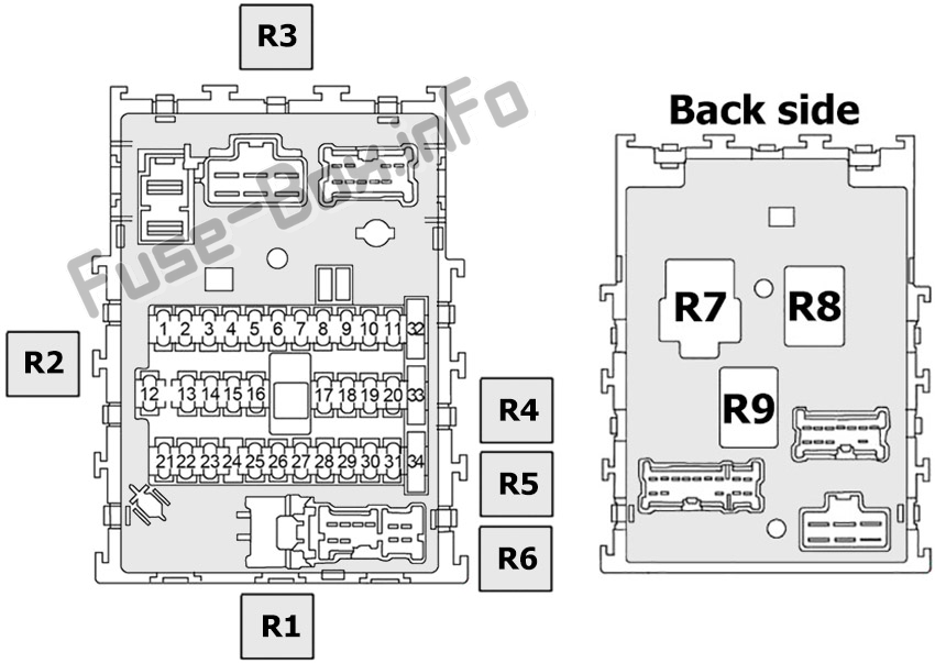
We have a copy of the 2004 Nissan Sentra Fuse Box Diagram available for download. This diagram provides detailed information about the location and function of each fuse and relay in your vehicle. Refer to it when doing your maintenance and repair.