Fuse Panel 2005 Nissan Maxima Fuse Box Diagram
So, you're diving into the fuse panel of your 2005 Nissan Maxima, huh? Good on you! Understanding your car's electrical system is crucial for everything from basic repairs to cool modifications. This guide will be your roadmap to deciphering the fuse box diagram, empowering you to diagnose electrical issues with confidence.
Purpose of the Fuse Box Diagram
The fuse box diagram is essentially a legend that identifies each fuse and relay within the fuse panel. Why is this important? Well, imagine an electrical component fails – your headlights, radio, or even something critical like the fuel pump. The first step is often to check the fuse associated with that circuit. Without the diagram, you're just guessing, potentially pulling out perfectly good fuses and wasting time. The diagram allows for efficient troubleshooting and avoids unnecessary expenses. A clear understanding of the diagram is not only beneficial for repairs, but also for learning about the vehicle's electrical system, identifying potential modifications or adding aftermarket accessories safely.
Key Specs and Main Parts
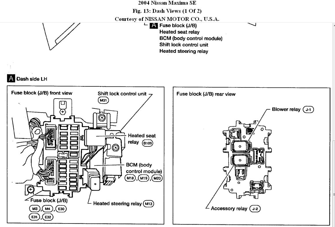
The 2005 Nissan Maxima typically has two main fuse boxes. One is usually located in the passenger compartment, often under the dashboard on the driver's side or behind the glove compartment. The other is in the engine compartment, near the battery. Each fuse box has its own distinct diagram.
Here's a breakdown of the key specs and components you'll encounter:
- Fuses: These are the sacrificial components designed to protect electrical circuits from overcurrents. They come in various amperage ratings (e.g., 5A, 10A, 15A, 20A, 30A). If the current exceeds the fuse's rating, the internal element melts, breaking the circuit and preventing damage to other components.
- Relays: These are electrically operated switches. They allow a low-current circuit to control a high-current circuit. For example, the low-current circuit from the headlight switch activates a relay, which then allows the high-current circuit to power the headlights.
- Fuse Puller: A small plastic tool designed to safely remove fuses without damaging them or yourself.
- Test Light or Multimeter: Essential tools for verifying if a fuse is blown and checking for voltage at various points in the circuit.
- The Diagram Itself: This is your key! It will list each fuse/relay and its corresponding circuit (e.g., "Headlight (Low Beam)," "Fuel Pump," "ABS").
Symbols – Deciphering the Diagram
Fuse box diagrams use symbols to represent different components and their connections. While the specifics can vary slightly, here's a general guide to interpreting common symbols:
- Lines: Solid lines generally represent wiring connections. Thicker lines may indicate higher current-carrying wires.
- Colors: Wire colors are often indicated on the diagram using abbreviations (e.g., "BL" for blue, "RD" for red, "BK" for black). These colors help you trace wires in the actual vehicle.
- Fuse Symbol: Typically represented by a zigzag line enclosed in a rectangle. The amperage rating is usually indicated next to the symbol.
- Relay Symbol: Often shown as a coil with a switch. The coil represents the relay's electromagnet, and the switch indicates the contacts that open or close the circuit.
- Ground Symbol: A series of lines decreasing in size, representing the connection to the vehicle's chassis (ground).
- Component Symbols: Other symbols might represent specific components like lights, motors, or sensors. These are often simplified representations of the actual part. For example, a light bulb symbol represents headlights or tail lights.
Important Note: Always refer to the specific diagram for your 2005 Nissan Maxima, as variations can exist based on trim level and options. Avoid using generic diagrams found online, as they may not be accurate. We have the correct diagram file available for download, so you can be sure you're working with the right information.
How It Works
The fuse box acts as the central distribution point for electrical power in your Maxima. Power flows from the battery, through the main wiring harness, and into the fuse boxes. From there, the power is distributed to various circuits, each protected by a fuse. When a component demands power, the circuit is completed, allowing current to flow. If a short circuit or overload occurs (too much current flowing), the fuse blows, interrupting the flow and preventing damage to the wiring and component.
Relays are used to control circuits that require high current. For instance, the headlight switch sends a low-current signal to the headlight relay. The relay then closes, allowing the battery's full voltage to power the headlights. This prevents the headlight switch from having to handle the high current directly, which could damage the switch. Relays are also used for other high-power circuits, such as the starter motor, fuel pump, and air conditioning compressor.
Real-World Use – Basic Troubleshooting Tips
Here's how to use the fuse box diagram for troubleshooting:
- Identify the Problem: Determine which component is not working (e.g., turn signals, power windows).
- Locate the Corresponding Fuse: Consult the fuse box diagram to find the fuse associated with the faulty component. Ensure you are using the correct diagram for the fuse box you're inspecting (passenger compartment or engine compartment).
- Inspect the Fuse: Visually inspect the fuse. A blown fuse will usually have a broken filament or a dark, burned appearance.
- Test the Fuse: Use a test light or multimeter to confirm the fuse is blown. With a test light, clip the ground lead to a good ground point and touch the probe to both test points on the top of the fuse with the ignition on. If the light doesn't illuminate on both sides, the fuse is blown. With a multimeter, set it to continuity mode. Remove the fuse and probe both ends. A good fuse will show continuity (usually a beep or a reading close to zero ohms), while a blown fuse will show no continuity.
- Replace the Fuse: Replace the blown fuse with a new fuse of the same amperage rating. Never use a fuse with a higher amperage rating, as this could damage the circuit.
- Test the Component: After replacing the fuse, test the component to see if it's now working.
- If the Fuse Blows Again: If the new fuse blows immediately or shortly after being replaced, there is a short circuit in the wiring or a fault within the component itself. This requires further diagnosis and repair. Do not simply keep replacing fuses!
Safety – Highlight Risky Components
Working with electrical systems can be dangerous. Here are some safety precautions to keep in mind:
- Disconnect the Battery: Before working on any electrical circuits, disconnect the negative battery cable to prevent accidental shorts.
- Avoid Water: Never work on electrical systems in wet conditions.
- High-Voltage Components: Be extremely cautious around components that handle high voltage, such as the ignition system. These can deliver a dangerous shock.
- Airbag System: The airbag system is electrically activated. Improper handling can cause accidental deployment, resulting in serious injury. If you're working near airbag components, consult the service manual for proper precautions. Disconnecting the battery is crucial, but it may not be sufficient in all cases.
- Never Bypass a Fuse: Bypassing a fuse with a wire or other conductive material is extremely dangerous. It removes the circuit's protection against overcurrents and can lead to a fire.
Remember to always consult your vehicle's service manual for specific instructions and safety information. And as a reminder, we have the correct 2005 Nissan Maxima fuse box diagram ready for you to download. Having the right information is the first step to a successful and safe repair!