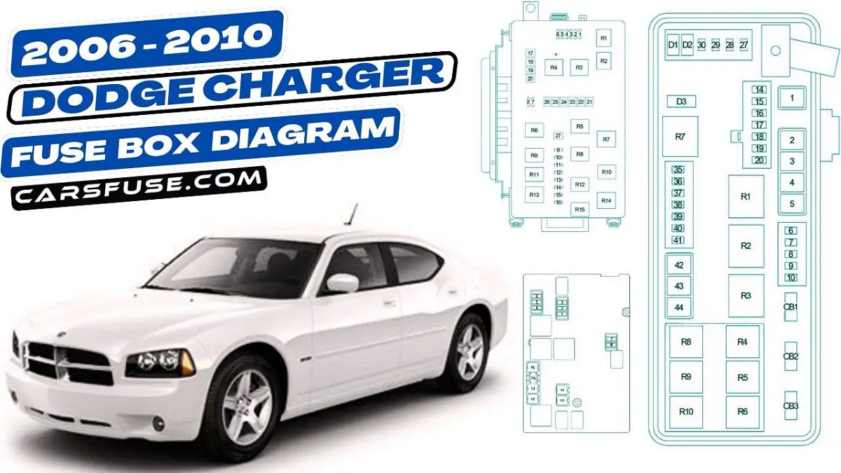
Fuse Panel 2006 Dodge Charger Fuse Box Diagram
For the DIY mechanic or car enthusiast tackling electrical work on a 2006 Dodge Charger, understanding the fuse panel and its corresponding fuse box diagram is absolutely crucial. It's your roadmap to troubleshooting electrical issues, performing safe modifications, and ensuring your Charger's systems operate as designed. This article provides a comprehensive guide to interpreting the 2006 Dodge Charger fuse box diagram, empowering you to confidently navigate its intricate network.
Purpose and Importance
The fuse box diagram for your 2006 Dodge Charger is far more than just a piece of paper. It's an essential tool for several reasons:
- Troubleshooting Electrical Problems: When an electrical component malfunctions – a headlight doesn't turn on, the radio is dead, or the windshield wipers won't work – the fuse box is the first place to check. The diagram allows you to quickly identify the fuse associated with that specific circuit and determine if it's blown.
- Safe Modifications: Adding aftermarket accessories like amplifiers, lights, or remote starters requires tapping into the electrical system. The diagram helps you identify appropriate circuits and correctly fuse your new additions, preventing overloads and potential electrical fires.
- Understanding Vehicle Systems: Studying the fuse box diagram provides valuable insight into how your Charger's various electrical systems are interconnected. This knowledge can be invaluable for diagnosing complex issues and performing more advanced repairs.
- Preventing Further Damage: Replacing a blown fuse with one of a higher amperage rating can overload the circuit and cause serious damage to wiring and components. The diagram ensures you use the correct fuse size for each circuit.
Key Specs and Main Parts of the Fuse Box
The 2006 Dodge Charger typically has two main fuse box locations:
- Underhood Fuse Box (Power Distribution Center - PDC): Located in the engine compartment, this houses the higher-amperage fuses and relays that protect critical systems like the engine control unit (ECU), starter, alternator, and ABS.
- Interior Fuse Box (Junction Block): Usually found inside the cabin, often under the dashboard on the driver's side, this fuse box protects circuits related to interior components like lights, radio, power windows, and door locks.
Key Specifications:
- Fuse Types: The 2006 Charger primarily uses blade-type fuses, also known as spade fuses. These come in various sizes (ATO, Mini, Maxi) and amperage ratings. The diagram will specify the correct type and amperage for each fuse.
- Amperage Ratings: Fuses are rated in amperes (A), indicating the amount of current they can safely handle before blowing. Common ratings include 5A, 10A, 15A, 20A, 25A, 30A, and 40A.
- Relays: Relays are electromagnetic switches used to control high-current circuits with low-current signals. They are commonly used for headlights, horns, and other power-intensive accessories. The diagram will identify the location and function of each relay.
Decoding the Fuse Box Diagram: Symbols, Lines, and Colors
The fuse box diagram is a schematic representation of the fuse panel's layout and the electrical circuits it protects. Understanding the symbols and notations is essential for accurate interpretation.
- Fuse Symbols: Fuses are typically represented by a simple rectangle or a zigzag line. The diagram will often include the fuse number and amperage rating next to the symbol.
- Relay Symbols: Relays are usually represented by a square with internal lines indicating the coil and switch contacts. The diagram will also show the relay's function and the circuit it controls.
- Lines: Lines on the diagram represent wiring. Thicker lines may indicate higher-gauge wiring used for high-current circuits.
- Colors: Some diagrams use color-coding to differentiate between circuits. For example, red might indicate a circuit powered directly from the battery, while blue might represent a circuit controlled by the ignition switch. Check the diagram's legend for specific color meanings.
- Icons/Labels: Each fuse and relay location is typically labeled with a description of the circuit it protects. These labels can be abbreviated, so it's important to refer to the diagram's legend for clarification. Examples include "IGN" for ignition, "PCM" for powertrain control module, "ABS" for anti-lock braking system, and "WIPER" for windshield wipers.
Example: A fuse labeled "IGN #2 - 10A" protects a 10-ampere circuit associated with the ignition system. If your car won't start, this would be a good fuse to check.
How It Works: Protecting Electrical Circuits
A fuse is a safety device designed to protect an electrical circuit from overcurrent. It contains a thin wire that melts and breaks the circuit when the current exceeds its rated amperage. This prevents damage to wiring, components, and potential electrical fires.
When a fuse blows, it indicates that there's an excessive current flow in the circuit. This can be caused by:
- Short Circuit: A short circuit occurs when a wire accidentally comes into contact with ground (the vehicle's chassis), creating a low-resistance path for current to flow.
- Overload: An overload occurs when too many devices are drawing current from the same circuit, exceeding its capacity.
- Component Failure: A faulty component, such as a motor or sensor, can draw excessive current and blow the fuse.
Real-World Use: Basic Troubleshooting Tips
Here's a step-by-step guide to troubleshooting a blown fuse using the fuse box diagram:
- Identify the Problem: Determine which component is not working.
- Locate the Fuse Box: Find the appropriate fuse box (underhood or interior).
- Consult the Diagram: Use the diagram to identify the fuse associated with the malfunctioning component. The diagram will usually be inside the fuse box cover.
- Inspect the Fuse: Remove the fuse using a fuse puller (usually included in the fuse box). Visually inspect the fuse. If the wire inside is broken or the glass is blackened, the fuse is blown.
- Replace the Fuse: Replace the blown fuse with a new fuse of the same amperage rating. Never use a fuse with a higher amperage rating.
- Test the Component: Turn on the component to see if it now works.
- If the Fuse Blows Again: If the new fuse blows immediately, there's likely a short circuit or overload in the circuit. Further diagnosis is required, possibly involving a multimeter to check for continuity and voltage.
Common Problems and Solutions:
- Headlights Not Working: Check the headlight fuses and relays in the underhood fuse box.
- Radio Not Working: Check the radio fuse in the interior fuse box.
- Power Windows Not Working: Check the power window fuses and possibly the power window relay in the interior fuse box.
Safety Considerations
Working with electrical systems can be dangerous. Here are some important safety precautions:
- Disconnect the Battery: Before working on any electrical circuits, disconnect the negative (-) battery cable to prevent accidental shorts and electric shock.
- Use Proper Tools: Use insulated tools designed for electrical work.
- Never Replace a Fuse with a Higher Amperage Rating: This can overload the circuit and cause serious damage or a fire.
- Avoid Working in Wet Conditions: Water can conduct electricity and increase the risk of electric shock.
- Be Cautious Around the Airbag System: The airbag system is a sensitive electrical system. Consult the service manual before working near any airbag components. Accidental deployment can cause serious injury. The airbag control module and related wiring are typically high-risk areas within the fuse panel and wiring harness.
High-Risk Components: Be particularly careful when working around the following components:
- Airbag Control Module: Located near or integrated within fuse panel, handle with extreme care to prevent accidental deployment.
- ECU (Engine Control Unit): The ECU controls critical engine functions and is sensitive to voltage fluctuations and shorts.
- ABS (Anti-lock Braking System) Module: The ABS module is responsible for controlling the braking system and should be handled with care.
By understanding your 2006 Dodge Charger's fuse box diagram and following these safety guidelines, you can confidently troubleshoot electrical problems, perform safe modifications, and keep your vehicle running smoothly. We have the complete, printable PDF diagram available for download to help with your projects. Refer to it frequently when working on your Charger's electrical system for accurate information and safe practices.