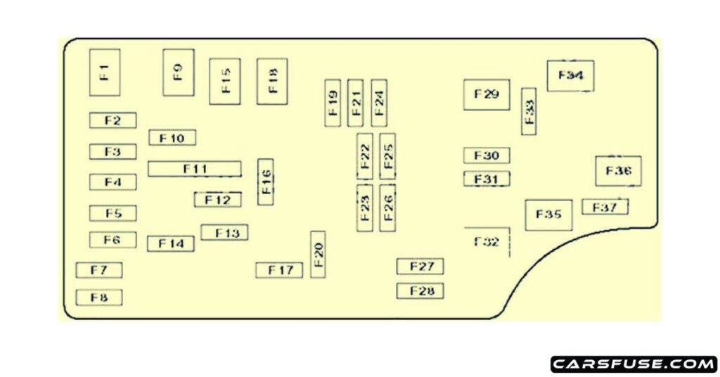
Fuse Panel 2008 Chrysler Sebring Fuse Box Diagram
Understanding your 2008 Chrysler Sebring's fuse panel is crucial for diagnosing electrical issues, performing modifications, and generally keeping your car running smoothly. This article provides an in-depth look at the fuse box diagram, covering its purpose, key components, how it works, and how to use it for troubleshooting. We'll break down the symbols and terminology, empowering you to confidently tackle electrical repairs on your Sebring. We also have the complete fuse box diagram available for download. Consider this your guide to demystifying your Sebring's electrical heart.
Purpose of the Fuse Panel Diagram
The fuse panel diagram is essentially a map of your car's electrical system. It identifies each fuse and relay, indicating which circuit each protects. This information is vital for several reasons:
- Troubleshooting Electrical Problems: When an electrical component fails (e.g., a headlight, the radio, or a power window), the fuse panel diagram helps you quickly identify the corresponding fuse for that circuit. Checking the fuse is the first step in diagnosing the problem.
- Performing Modifications: If you're adding aftermarket accessories like a new sound system, auxiliary lights, or a dashcam, the diagram helps you find appropriate circuits to tap into for power, ensuring you don't overload existing circuits.
- General Maintenance and Learning: Familiarizing yourself with the fuse panel and diagram allows you to better understand your car's electrical system, making you a more informed car owner.
- Replacing a blown fuse: Crucial step to fix a broken electrical component in the car.
Key Specs and Main Parts of the Fuse Panel
The 2008 Chrysler Sebring typically has two fuse panels:
- Interior Fuse Panel: Usually located inside the cabin, often behind a panel on the driver's side dashboard or under the steering wheel. This panel houses fuses and relays for interior systems like the radio, power windows, interior lights, and the cigarette lighter.
- Under-Hood Fuse Panel (Power Distribution Center): Located in the engine compartment, this panel contains larger fuses and relays that protect the car's primary electrical systems, such as the engine control unit (ECU), headlights, air conditioning, and the anti-lock braking system (ABS). This Power Distribution Center (PDC) is the main electrical hub of the vehicle.
Key Specs (Typical):
- Fuse Types: Blade-type fuses (ATO, Mini-ATO) are most common. These are standardized and color-coded by amperage.
- Voltage: The car's electrical system operates at 12 volts DC.
- Amperage Ratings: Fuses are rated in amperes (amps or A), indicating the maximum current they can handle before blowing. Common ratings include 5A, 7.5A, 10A, 15A, 20A, 25A, 30A, and 40A.
Main Parts:
- Fuses: These are sacrificial devices designed to protect circuits from overcurrent. When the current exceeds the fuse's rating, the fuse's filament melts, breaking the circuit and preventing damage to components.
- Relays: Electrically operated switches that control high-current circuits. They allow a low-current signal from a switch or ECU to activate a higher-current circuit, such as the headlights or starter motor.
- Fuse Puller: A small plastic tool included in the fuse box to safely remove fuses without damaging them.
- The Diagram: Usually a sticker located on the inside of the fuse box cover, detailing each fuse and relay's location and function.
Understanding Fuse Panel Symbols
Fuse panel diagrams use symbols to represent different components and electrical connections. Understanding these symbols is essential for interpreting the diagram correctly.
- Fuses: Usually represented by a rectangle with a squiggly line inside, symbolizing the fuse's filament.
- Relays: Often depicted as a square with a coil symbol inside, representing the relay's electromagnet. Sometimes shown as a series of interconnected squares.
- Ground Connections: Typically symbolized by a downward-pointing triangle or a series of horizontal lines that get progressively shorter, indicating a connection to the car's chassis, which serves as the ground for the electrical system.
- Wires: Shown as straight lines. Thicker lines may indicate wires that carry more current.
- Color Coding (Wires): Wire colors are often noted on more detailed diagrams or wiring schematics. These are not usually included on the fuse box diagram itself but are useful for tracing wires within the system.
- Icons: Many diagrams use icons to represent the components protected by each fuse. For example, a headlight icon indicates the headlight circuit, a steering wheel icon indicates the power steering circuit, and so on.
Note on Color Coding: While the fuse housing itself is color-coded to indicate amperage (e.g., yellow for 20A), the wiring may not strictly adhere to this. Always double-check the diagram and fuse rating before replacing a fuse.
How It Works: The Electrical Flow
The car's battery provides the initial power source. This power flows through the main wiring harness to the fuse panels. Each circuit is protected by a fuse. When a circuit experiences an overcurrent condition (e.g., a short circuit or excessive load), the fuse blows, interrupting the flow of electricity and preventing damage to the wiring and components. Relays act as switches controlled by the ECU or other control modules. They allow low-current signals to control high-current circuits, activating components like the starter motor, headlights, or fuel pump.
Understanding this basic flow is key to troubleshooting. For example, if your headlights aren't working, you would first consult the fuse panel diagram to identify the headlight fuse. If the fuse is blown, replacing it *might* solve the problem. However, if the fuse blows again immediately, it indicates a more serious issue, such as a short circuit in the headlight wiring or a faulty headlight bulb drawing excessive current. Then you might consult the diagram again to check all of the associated relays for damage.
Real-World Use: Basic Troubleshooting Tips
Here are some basic troubleshooting tips using the fuse panel diagram:
- Identify the Problem: Determine which electrical component is not working.
- Consult the Diagram: Locate the fuse or relay associated with the non-working component.
- Inspect the Fuse: Remove the fuse using the fuse puller. Visually inspect the filament. If the filament is broken or the fuse is blackened, it's blown.
- Replace the Fuse: Replace the blown fuse with a new fuse of the exact same amperage rating. Do not use a higher amperage fuse, as this could damage the wiring and components.
- Test the Component: Turn on the component to see if it now works.
- If the Fuse Blows Again: This indicates a short circuit or other electrical problem. You'll need to investigate further to find the cause of the overcurrent. This might involve checking the wiring for damage, inspecting the component itself, or consulting a professional mechanic.
Safety Precautions
Working with your car's electrical system can be dangerous. Here are some important safety precautions:
- Disconnect the Battery: Before working on any electrical components, disconnect the negative (-) battery cable to prevent accidental shorts or electrical shocks.
- Never Use a Higher Amperage Fuse: Using a fuse with a higher amperage rating than specified can overload the circuit and cause a fire.
- Avoid Tampering with Relays: Relays control high-current circuits and can be dangerous to work with. If you suspect a relay is faulty, replace it with a new one of the correct type.
- Be Careful Around High-Voltage Components: The ignition system and fuel injection system contain high-voltage components that can deliver a painful shock. Avoid touching these components unless you are trained to do so.
- Protect yourself with Gloves and Eyewear: Always wear appropriate personal protective equipment, like gloves and eye protection, while working on your car.
Specifically, be careful when dealing with the ABS (Anti-lock Braking System) module. Faulty ABS components can be dangerous and should be handled with extreme care, or preferably by a qualified mechanic. The airbags are also sensitive to electrical disturbances and should only be handled by someone with specialized training.
We have the complete fuse box diagram file available for download. This diagram will provide you with a detailed map of your 2008 Chrysler Sebring's fuse panels, enabling you to confidently troubleshoot electrical issues and perform modifications.