Fuse Panel 2010 Ford Escape Fuse Box Diagram
Alright, let's dive into the fuse panel diagram for a 2010 Ford Escape. Whether you're chasing down a pesky electrical gremlin, planning some aftermarket modifications, or just want to understand your vehicle a bit better, knowing your way around the fuse box is essential. This isn't about becoming a certified electrician overnight, but about empowering you with the knowledge to diagnose and potentially fix common issues, or at least understand what's going on when you take it to a professional.
Purpose of the Fuse Panel Diagram
Why bother with a fuse panel diagram in the first place? The primary reason is simple: troubleshooting electrical problems. When something electrical stops working in your Escape – headlights, radio, power windows, etc. – the first thing you should check is the corresponding fuse. The diagram tells you precisely which fuse to examine. Without it, you're essentially playing a guessing game, pulling fuses at random, which is time-consuming and can even introduce new problems. Beyond repairs, the diagram is invaluable for:
- Planning modifications: Adding aftermarket lights, a new stereo, or other electrical accessories requires tapping into the car's electrical system. The diagram helps you identify the appropriate circuits and ensure you're not overloading anything.
- Understanding your vehicle: Simply put, knowing what each fuse protects gives you a better understanding of how your car's electrical system is organized. This can be helpful in various situations.
- Preventative maintenance: Periodically checking your fuses for corrosion or damage can help you identify potential problems before they become major headaches.
Key Specs and Main Parts of the 2010 Ford Escape Fuse Box
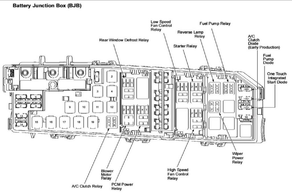
The 2010 Ford Escape, like most vehicles, typically has two main fuse boxes. Understanding their location and general function is crucial:
- Engine Compartment Fuse Box: Located under the hood, this box houses fuses and relays for circuits related to the engine, transmission, cooling system, and other critical vehicle systems. Expect to find fuses related to the fuel pump, ignition system, cooling fan, and various sensors here.
- Passenger Compartment Fuse Box: Usually found under the dashboard, often near the driver's side kick panel, this box protects circuits related to interior components like the radio, power windows, door locks, instrument cluster, and interior lighting.
The diagram itself provides a visual representation of these boxes, showing the location of each fuse and relay. It also includes a legend that lists each fuse or relay and its corresponding circuit. This legend is the key to deciphering the diagram.
Key Specs: While the voltage rating is standard across the board (12V DC), the amperage rating of each fuse is critical. Common fuse amperage ratings you'll encounter include 5A, 7.5A, 10A, 15A, 20A, 25A, and 30A. Using a fuse with a higher amperage rating than specified can be extremely dangerous and can lead to overheating and potential fire. Always replace a blown fuse with one of the exact same amperage.
Symbols and Conventions Used in the Fuse Diagram
Fuse diagrams use a standardized set of symbols and conventions to represent different components and connections. Here's a breakdown of common elements:
- Lines: Solid lines typically represent wires or electrical conductors. Dotted lines might indicate a ground connection or a shielded wire.
- Colors: Wire colors are often indicated on the diagram using abbreviations (e.g., RD for red, BL for blue, BK for black). Knowing the wire color can be helpful for tracing circuits.
- Fuse Symbol: A wavy line enclosed in a rectangle is the standard symbol for a fuse. The amperage rating is usually printed next to the fuse symbol on the diagram.
- Relay Symbol: Relays are typically represented by a square or rectangle with a coil symbol inside. Relays are electromechanical switches that allow a low-current circuit to control a high-current circuit.
- Ground Symbol: The ground symbol usually resembles a series of downward-pointing lines or a triangle connected to a line. It indicates a connection to the vehicle's chassis, which serves as the electrical ground.
- Component Symbols: Various symbols represent electrical components like lights, motors, switches, and sensors. These symbols may vary slightly depending on the diagram. Refer to the diagram's legend for clarification.
Understanding Amperage and Circuit Protection: Each circuit in your car is designed to handle a certain amount of current (measured in Amperes). The fuse acts as a sacrificial component. If the current exceeds the fuse's rating, the fuse blows, breaking the circuit and preventing damage to the wiring and components. This is why it's absolutely critical to use the correct amperage fuse. Using a higher amperage fuse allows more current to flow, potentially overheating the wiring and causing a fire.
How It Works: A Simplified Explanation
The fuse box acts as a central distribution point for electrical power in your vehicle. Power flows from the battery through the wiring harness to the fuse box. Within the fuse box, each circuit is protected by a fuse. When you turn on a switch (e.g., headlights), you complete a circuit, allowing current to flow from the battery, through the fuse, through the wiring to the headlights, and back to the battery through the ground. If there's a short circuit (e.g., a wire chafing against the chassis), the sudden surge of current will blow the fuse, preventing further damage. The relay acts as a switch to control higher current devices such as headlights, air conditioning and starter motor.
Real-World Use: Basic Troubleshooting Tips
Here's a basic troubleshooting scenario:
- Symptom: Your radio suddenly stops working.
- Consult the Diagram: Locate the passenger compartment fuse box diagram.
- Identify the Fuse: Find the fuse labeled "Radio" or "Audio System" on the diagram. Note its amperage rating.
- Inspect the Fuse: Visually inspect the fuse. A blown fuse will have a broken filament or a dark, burned appearance.
- Replace the Fuse: Replace the blown fuse with a new fuse of the exact same amperage rating.
- Test: Turn on the radio. If it works, you've solved the problem.
- Persistent Problem: If the new fuse blows immediately or soon after, there's a deeper issue. This indicates a short circuit in the radio wiring or the radio itself. Further diagnosis is required, potentially involving a multimeter and circuit tracing.
Important Tools: A multimeter is invaluable for electrical troubleshooting. It allows you to measure voltage, current, and resistance, helping you pinpoint the source of the problem. A fuse puller (a small plastic tool designed to grip and remove fuses) is also a handy tool to avoid damaging the fuses or the fuse box connectors.
Safety Considerations
Working with electrical systems always carries some risk. Here are some crucial safety precautions:
- Disconnect the Battery: Before working on any electrical system, disconnect the negative (black) battery cable. This prevents accidental shorts and electrical shocks.
- Proper Tools: Use insulated tools designed for electrical work.
- Never Bypass a Fuse: Don't be tempted to bypass a fuse with a piece of wire or a higher amperage fuse. This is extremely dangerous and can cause a fire.
- High-Voltage Components: Be aware of high-voltage components like the ignition system and the airbag system. These components can deliver a dangerous shock, even with the battery disconnected. Consult a qualified technician if you need to work on these systems.
Risky Components: The airbag system is particularly sensitive. Improper handling can cause the airbags to deploy unexpectedly, resulting in serious injury. If you need to work near the airbag system, consult a professional.
Disclaimer: This information is intended for educational purposes only. Automotive electrical systems can be complex, and improper repairs can be dangerous. If you are not comfortable working on your vehicle's electrical system, consult a qualified mechanic.
We have the complete fuse panel diagram available for download. Use it wisely and safely!