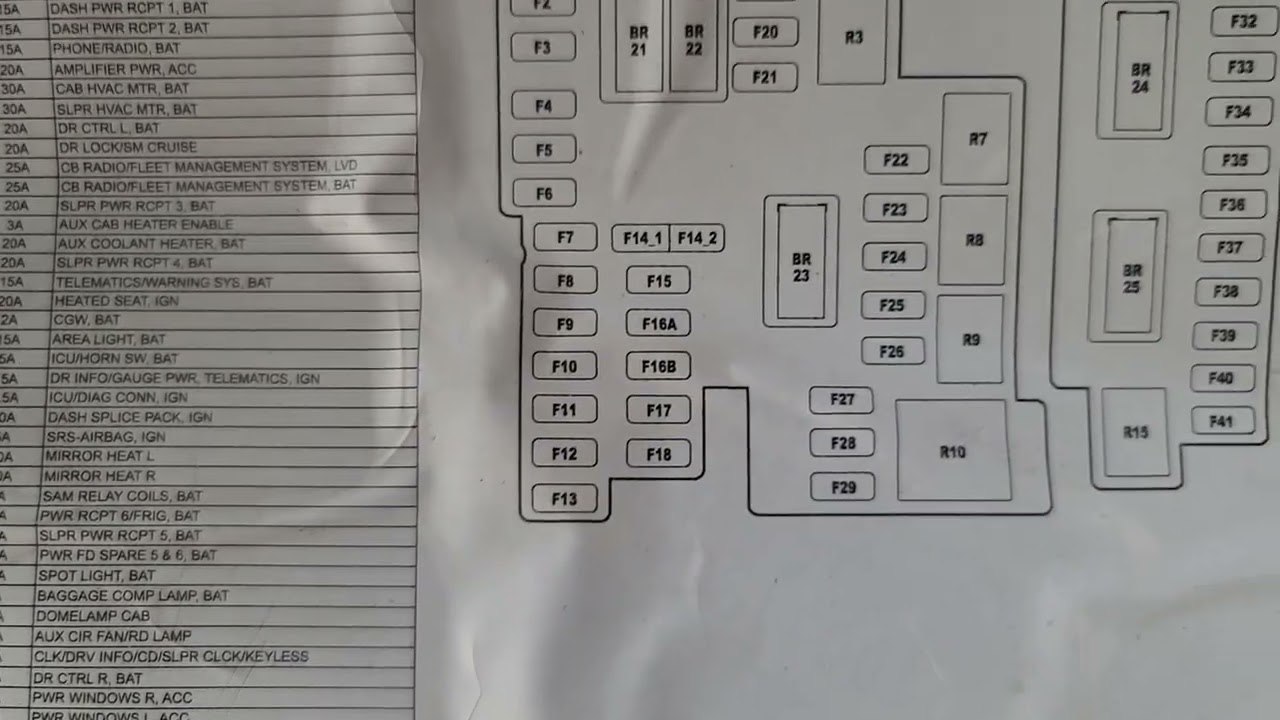
Fuse Panel 2016 Freightliner Cascadia Fuse Box Diagram
Alright, let's dive into the fuse panel diagram for your 2016 Freightliner Cascadia. This isn't just a pretty picture; it's your roadmap to electrical troubleshooting, modifications, and understanding how your truck's systems are protected. Whether you're dealing with a blown fuse, planning to add some aftermarket accessories, or just want to familiarize yourself with the electrical guts of your beast, this guide will break down the essentials.
Why This Diagram Matters
Think of your fuse panel diagram as the Rosetta Stone of your truck's electrical system. Without it, you're fumbling in the dark. Specifically, it allows you to:
- Quickly Identify Blown Fuses: Instead of guessing, the diagram pinpoints the circuit associated with each fuse.
- Perform Accurate Repairs: Knowing what a fuse protects prevents misdiagnosis and potentially costly mistakes.
- Plan Modifications Safely: Adding accessories requires tapping into existing circuits. The diagram shows you the available amperage and prevents overloading.
- Increase Your Truck Knowledge: Understanding the layout of your electrical system is empowering and can save you money on future repairs.
Key Specs and Main Parts of the Fuse Panel
The 2016 Freightliner Cascadia typically has multiple fuse panels, often located in the cab (under the dash or in a side compartment) and potentially one in the engine compartment. The diagrams we're referring to will generally cover the main cab fuse panel, which controls most of the essential systems. Here's what you need to know:
Fuse Types:
Your Cascadia likely uses a mix of fuse types. Common ones include:
- Blade Fuses (ATO/ATC): These are the standard, color-coded fuses with two prongs that plug into the panel. Amperage rating is indicated by color and often printed on the fuse itself.
- Mini Blade Fuses: Smaller versions of blade fuses, often used in newer vehicles to save space.
- Maxi Fuses: Larger blade fuses with higher amperage ratings, typically used for high-current circuits like the starter or main power feeds.
- Cartridge Fuses: Enclosed in a rectangular housing, often used for high-current circuits as well, especially in the engine compartment.
Key Components:
- Fuse Block: The plastic housing that holds the fuses and provides the electrical connections.
- Fuses: The sacrificial components designed to protect circuits from overcurrent.
- Relays: Electrically operated switches that control high-current circuits using a low-current signal. Relays are often located near the fuse panel.
- Wiring Harness Connectors: Connectors that bring power and ground to the fuse panel.
- Grounding Points: Essential for completing the circuit and ensuring proper operation. Poor grounding can cause all sorts of electrical issues.
Amperage Ratings:
Each fuse has an amperage rating, indicating the maximum current it can handle before blowing. Never replace a fuse with one that has a higher amperage rating. Doing so can bypass the circuit protection and cause serious damage, including electrical fires.
Decoding the Symbols
The fuse panel diagram isn't just a bunch of lines and boxes; it's a language. Let's translate some common symbols:
- Solid Lines: Represent wires carrying electrical current. Thicker lines often indicate higher current capacity.
- Dashed Lines: May indicate shielded wiring or a control signal rather than a direct power feed.
- Boxes with Numbers: These represent the fuses themselves. The number inside the box is the fuse number, which corresponds to the legend on the diagram.
- Circles or Ovals: Can represent various components, depending on what they contain. Check the legend for specific meanings (e.g., a sensor, a switch).
- Ground Symbol (usually three horizontal lines decreasing in length): Indicates a connection to the vehicle's chassis ground.
- Color Codes: Wires are often color-coded. The diagram should include a key indicating what each color represents (e.g., Red = Battery +, Black = Ground, etc.).
- Icons: Small pictures representing the component protected by the fuse (e.g., a headlight, a wiper blade, a radio).
Crucially, the legend or key is your best friend. It will define all the symbols and abbreviations used on the diagram. Without it, you're essentially guessing.
How It Works: The Fuse Panel in Action
The fuse panel acts as a central distribution point for electrical power in your Cascadia. Here's the basic flow:
- Power Source: The battery provides the initial electrical power.
- Main Power Feed: A heavy-gauge wire carries power from the battery to the fuse panel, often protected by a high-amperage fuse or circuit breaker near the battery.
- Distribution: Inside the fuse panel, the power is distributed to various circuits, each protected by its own fuse.
- Component Activation: When a switch is turned on (e.g., headlights), current flows through the circuit, powering the corresponding component.
- Overcurrent Protection: If a fault occurs in the circuit (e.g., a short to ground), the current draw increases dramatically. The fuse blows, interrupting the circuit and preventing damage.
Relays play a vital role in many of these circuits. They allow a low-current switch to control a high-current load. For example, the headlight switch doesn't directly power the headlights; it energizes a relay that then switches on the high-current headlight circuit.
Real-World Use: Basic Troubleshooting
Let's say your windshield wipers suddenly stop working. Here's how to use the fuse panel diagram to troubleshoot:
- Consult the Diagram: Locate the fuse associated with the windshield wipers on the diagram.
- Inspect the Fuse: Remove the fuse and visually inspect it. A blown fuse will have a broken filament (the thin wire inside).
- Replace the Fuse: If the fuse is blown, replace it with a new fuse of the same amperage rating.
- Test the System: Turn on the windshield wipers to see if they now work.
- If the Fuse Blows Again: If the new fuse immediately blows, there's a short circuit in the wiper circuit. This requires further investigation, such as checking the wiring and the wiper motor itself. This might involve using a multimeter to check for continuity to ground.
Important: Before replacing any fuse, make sure the ignition is off and the electrical load is switched off, too.
Safety First!
Working with electrical systems can be dangerous. Here are some crucial safety precautions:
- Disconnect the Battery: Before performing any major electrical work, disconnect the negative battery cable to prevent accidental shorts.
- Use Insulated Tools: Always use tools with insulated handles to protect yourself from electric shock.
- Avoid Working in Wet Conditions: Water conducts electricity. Never work on electrical systems in the rain or near standing water.
- Identify High-Voltage Components: Be aware of components that carry high voltage, such as the ignition system and certain lighting circuits. These can deliver a dangerous shock even with the battery disconnected.
- Don't Bypass Fuses: Never bypass a fuse with a wire or other conductive material. This eliminates the circuit protection and can lead to serious damage or fire.
The starter circuit is especially risky due to the high amperage involved. Be extremely cautious when working on this circuit.
Remember, if you're not comfortable working on electrical systems, it's always best to consult a qualified mechanic.
We have the fuse panel diagram for the 2016 Freightliner Cascadia available for download. Please reach out, and we will gladly share the file with you.