
Gas Water Heater Control Valve Diagram
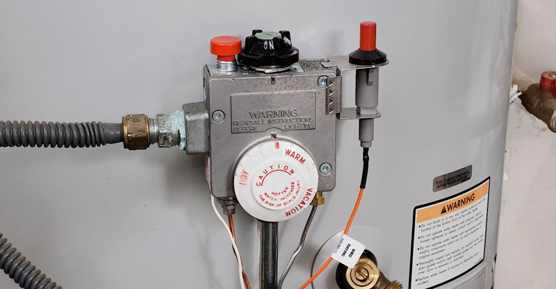
Understanding the control valve on a gas water heater is crucial for anyone undertaking DIY repairs or simply wanting to grasp the inner workings of their home's heating system. A gas water heater control valve diagram provides a roadmap to this vital component, enabling you to diagnose issues, perform basic troubleshooting, and even plan for replacements. This article will break down the diagram, explaining its components, symbols, and functions in a clear and approachable manner.
Purpose of a Gas Water Heater Control Valve Diagram
Why bother with a diagram? Quite simply, it's your key to understanding and working on your gas water heater's control valve. Here's why a diagram is invaluable:
- Troubleshooting: The diagram allows you to trace the flow of gas and electrical signals, helping you pinpoint the source of a problem, whether it's a pilot light that won't stay lit, insufficient hot water, or a complete system failure.
- Repairs: When replacing parts or performing repairs, the diagram ensures you connect everything correctly. It's a visual guide to prevent accidental damage or gas leaks.
- Learning: Even if you don't plan on doing repairs yourself, understanding the diagram provides a better understanding of your water heater's operation and how to identify potential issues early on.
- DIY Projects: If you're customizing your system (although we strongly advise against modifying safety features unless you're a qualified professional!), a diagram is essential for planning and execution.
Key Specs and Main Parts of a Gas Water Heater Control Valve
Before diving into the diagram, let's define the key components of a typical gas water heater control valve. Remember, specific designs may vary slightly between manufacturers and models, but the fundamental principles remain the same.
- Gas Inlet: The connection point for the main gas supply line. This is where natural gas or propane enters the valve.
- Gas Outlet: The connection point where gas flows from the valve to the burner assembly.
- Thermocouple/Flame Sensor: A safety device that detects the presence of the pilot light flame. If the pilot light goes out, the thermocouple shuts off the gas supply to prevent a gas leak. Some newer units use electronic flame sensors.
- Thermopile (in some models): Generates a small electrical current to power the control valve's internal components. It's heated by the pilot light.
- Temperature Sensor (Thermostat): A device that monitors the water temperature inside the tank. When the water temperature drops below the set point, the thermostat signals the valve to open the gas supply to the burner.
- Temperature Adjustment Dial: Allows you to set the desired water temperature.
- Pilot Gas Tubing: A small-diameter tube that carries gas to the pilot burner.
- Pilot Burner: A small burner that provides a constant flame to ignite the main burner.
- Main Burner: The primary burner that heats the water.
- Pressure Regulator: Maintains a constant gas pressure to the burner, ensuring consistent heating.
- Manual Shut-Off Valve: Allows you to completely shut off the gas supply to the water heater for maintenance or emergencies.
- Draft Diverter: Part of the flue that directs exhaust gases upward and away from the unit. (While not part of the valve itself, it's an important safety component shown on many diagrams).
Understanding the Symbols in the Diagram
A gas water heater control valve diagram uses standardized symbols to represent different components and connections. These symbols are essential for interpreting the diagram accurately.
- Lines: Represent gas lines, electrical wires, or mechanical linkages. The thickness of the line may indicate the size or importance of the connection.
- Solid Lines: Typically indicate gas lines carrying fuel.
- Dashed Lines: Usually represent electrical wiring or sensor connections.
- Dotted Lines: Can represent mechanical linkages or less critical connections.
- Arrows: Indicate the direction of gas flow or electrical current.
- Circles: Often represent sensors, switches, or adjustment knobs.
- Rectangles: Can represent electronic components or valve bodies.
- Triangles: Often used to represent thermocouples or thermopiles.
- Colors: Some diagrams use color-coding to distinguish between different types of connections. For example:
- Red: Often indicates the main gas supply line.
- Blue: May indicate the pilot gas line.
- Black: Usually represents ground wires.
- White: Often represents neutral wires.
- Icons: Symbols that represent the components of the diagram, such as:
- A flame indicates the burners
- A thermostat represents the temperature control
The legend of the diagram will explain what each symbol means. Always refer to the specific legend for your model.
How It Works: The Gas Water Heater Control Valve in Action
The control valve orchestrates the entire water heating process. Here's a simplified breakdown:
- Pilot Light Ignition: The pilot light is initially lit manually (or electronically in some models). The thermocouple/flame sensor is heated by the pilot flame.
- Thermocouple Activation: The heated thermocouple generates a small electrical current. This current keeps the pilot gas valve open, allowing the pilot light to remain lit.
- Temperature Sensing: The thermostat constantly monitors the water temperature in the tank.
- Call for Heat: When the water temperature drops below the set point on the temperature adjustment dial, the thermostat signals the control valve to open the main gas valve.
- Main Burner Ignition: Gas flows from the main gas valve to the main burner. The pilot light ignites the gas, and the main burner heats the water.
- Maintaining Temperature: The thermostat continues to monitor the water temperature. When the desired temperature is reached, the thermostat signals the control valve to close the main gas valve, shutting off the burner. The pilot light remains lit, ready to ignite the main burner when needed.
- Safety Shutoff: If the pilot light goes out, the thermocouple cools down, stopping the electrical current. This causes the pilot gas valve to close, shutting off the gas supply to both the pilot and main burners, preventing a gas leak.
Real-World Use: Basic Troubleshooting Tips
Here are a few common problems you might encounter and how the diagram can help you troubleshoot them:
- Pilot Light Won't Stay Lit: Check the thermocouple (using a multimeter to verify its output). The diagram shows you exactly where it's located and how it connects to the control valve. Also check the pilot gas tubing for blockages.
- No Hot Water: Verify that the thermostat is set correctly. If it is, use the diagram to trace the connections between the thermostat and the control valve. A faulty thermostat or a problem with the wiring could be the cause. Also check the gas supply and the main burner to ensure it is operating.
- Insufficient Hot Water: Check the temperature setting on the control valve. If that's not the issue, the heating element may be failing, or the tank may be accumulating sediment. The diagram won't help with sediment buildup, but it can guide you in testing the thermostat.
Safety: Risky Components and Precautions
Gas and electricity are dangerous! Before working on any gas appliance, take the following precautions:
- Turn Off the Gas Supply: Locate the manual shut-off valve on the gas supply line to the water heater and turn it off completely.
- Turn Off the Electrical Power: Locate the circuit breaker for the water heater and turn it off.
- Ventilate the Area: Open windows and doors to provide adequate ventilation.
- Use a Gas Leak Detector: After making any connections, use a gas leak detector or soapy water to check for leaks.
- Call a Professional: If you are not comfortable working with gas or electricity, do not attempt the repair yourself. Contact a qualified technician.
The most risky components include:
- Gas Lines: Any leaks in gas lines can create a fire or explosion hazard.
- Electrical Connections: Incorrect wiring can cause electric shock or damage the water heater.
- Burner Assembly: Improperly installed or maintained burner assemblies can cause carbon monoxide poisoning.
Remember, safety is paramount. When in doubt, consult a qualified technician.
We have access to a comprehensive gas water heater control valve diagram. If you're a DIY enthusiast looking to further your understanding and gain access to valuable resources, feel free to reach out, and we'll provide you with access.