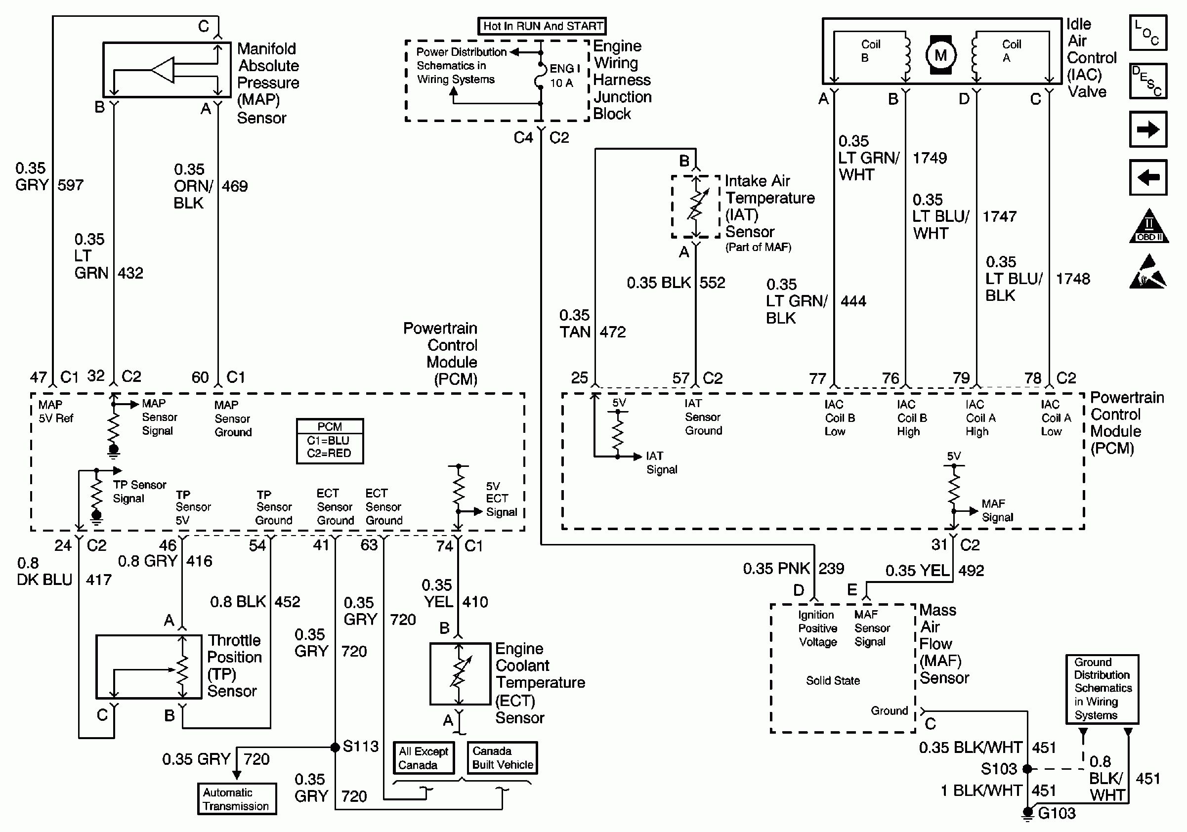
Gm Accelerator Pedal Position Sensor Wiring Diagram
Alright, let's dive into the intricacies of a GM accelerator pedal position (APP) sensor wiring diagram. Whether you're tackling a frustrating check engine light, contemplating a performance modification, or simply want a deeper understanding of your vehicle's inner workings, grasping this diagram is crucial. Think of it as the roadmap to your engine's throttle control – miss a turn, and you end up in the wrong place. This article aims to provide you, the experienced DIYer, with the knowledge to confidently navigate this seemingly complex circuit.
Why This Diagram Matters
The APP sensor wiring diagram isn't just a pretty picture; it's your key to:
- Troubleshooting: Pinpointing electrical faults causing poor acceleration, surging, or limp mode.
- Repairs: Identifying damaged wires, faulty connectors, or a failing sensor itself.
- Modification: Safely integrating aftermarket components like throttle controllers or performance chips (proceed with caution!).
- Understanding: Gaining a comprehensive view of how your engine management system operates.
In essence, having a solid understanding of the APP sensor wiring diagram allows you to diagnose and resolve issues efficiently, saving you time and money. It also empowers you to make informed decisions about modifications, ensuring compatibility and safety.
Key Specs and Main Parts
Before we dissect the diagram itself, let's define the key components involved:
- Accelerator Pedal Position (APP) Sensor: This is the star of the show. It's a potentiometer (or sometimes multiple potentiometers for redundancy) that converts the position of the accelerator pedal into an electrical signal. This signal tells the engine control module (ECM) how much the driver wants to accelerate.
- Engine Control Module (ECM): The brain of the operation. The ECM receives the APP sensor signals, along with other inputs, and calculates the appropriate throttle opening, fuel injection, and ignition timing.
- Wiring Harness: The nervous system. A network of wires connecting the APP sensor to the ECM and other relevant components.
- Connectors: Where the wires meet the components. Clean, secure connectors are vital for reliable signal transmission.
Typical APP sensors on GM vehicles have 5-6 wires, each serving a specific purpose:
- Sensor 1 Signal: The primary signal indicating pedal position.
- Sensor 2 Signal: A redundant signal for cross-checking and fault detection. This is especially important in drive-by-wire systems where there's no direct mechanical connection.
- 5V Reference Voltage: A stable 5-volt power supply provided by the ECM to the APP sensor.
- Low Reference/Ground: The ground connection for the APP sensor.
- (Sometimes) APP Sensor Return: A dedicated return wire for the sensor signal, improving signal accuracy.
- (Sometimes) Idle Validation Switch: Indicates when the pedal is fully released (at idle).
Decoding the Symbols: Your Wiring Diagram Rosetta Stone
Understanding the symbols in the wiring diagram is key to interpreting it correctly. Here's a breakdown of common symbols you'll encounter:
- Solid Lines: Represent wires. The thickness of the line usually doesn't indicate wire gauge, but simply clarity on the diagram.
- Dashed Lines: Often represent shielding or twisted pairs of wires, which are used to reduce electromagnetic interference (EMI).
- Colors: Extremely important! Each wire is color-coded (e.g., Red, Black, Blue/White). Pay close attention to these, as incorrect connections can cause serious damage. Common abbreviations include: BLK (Black), RED (Red), GRN (Green), BLU (Blue), WHT (White), YEL (Yellow), BRN (Brown), ORG (Orange).
- Circles/Squares with Numbers: Indicate connector pin numbers. These are crucial for identifying the correct wires at the connector.
- Ground Symbol (Typically three horizontal lines decreasing in size): Represents a connection to the vehicle's chassis ground.
- Voltage Source Symbol (Line with plus sign): Represents a voltage source (typically 5V or 12V).
- Component Symbols: Each component (APP sensor, ECM, etc.) is represented by a distinct symbol, usually a simplified illustration of the component.
Beyond the basic symbols, be aware of abbreviations like:
- ECM/PCM: Engine Control Module/Powertrain Control Module
- APP: Accelerator Pedal Position
- VREF: Voltage Reference
- GND: Ground
How It Works: From Pedal to Power
The APP sensor system operates on a relatively straightforward principle. When you press the accelerator pedal, the APP sensor detects the change in position. This change is converted into two analog voltage signals (Sensor 1 and Sensor 2). These signals are sent to the ECM.
The ECM then uses these signals, along with data from other sensors (e.g., engine speed, air flow), to determine the optimal throttle position. The ECM then controls the throttle body, allowing the engine to generate the desired power.
The two APP sensor signals are crucial for redundancy and error detection. The ECM constantly monitors both signals. If the signals deviate significantly from each other (beyond a predetermined tolerance), the ECM interprets this as a fault and may trigger a check engine light and/or enter a limp mode (reduced engine power) to prevent potential damage or unsafe operation.
In drive-by-wire systems, the APP sensor directly controls the throttle body via an electric motor. There's no direct mechanical linkage between the pedal and the throttle. This makes accurate and reliable APP sensor signals even more critical.
Real-World Use: Basic Troubleshooting
Here are some basic troubleshooting tips using the APP sensor wiring diagram:
- Check for DTCs: Use an OBD-II scanner to retrieve diagnostic trouble codes (DTCs). Codes like P0120, P0121, P0122, P0123, P0128, P2122, P2123, P2135, and P2138 are commonly associated with APP sensor issues.
- Visual Inspection: Inspect the wiring harness and connectors for any signs of damage, corrosion, or loose connections. Pay particular attention to the connector at the APP sensor.
- Voltage Testing: Use a multimeter to check the voltage at the APP sensor connector. Verify the presence of the 5V reference voltage and ground. Also, check the signal voltage at both Sensor 1 and Sensor 2 while slowly depressing the accelerator pedal. The voltage should change smoothly and proportionally to pedal position. Refer to your vehicle's service manual for specific voltage ranges.
- Continuity Testing: With the ignition off and the APP sensor disconnected, use a multimeter to check the continuity of the wires between the APP sensor connector and the ECM connector. This helps identify broken or shorted wires.
- Connector Cleaning: Clean the APP sensor connector and the ECM connector with electrical contact cleaner. Corrosion can significantly impair signal transmission.
Example Scenario: You have a DTC P2135 (Throttle/Pedal Position Sensor/Switch A/B Voltage Correlation). Using the wiring diagram, you would first locate the APP sensor connector and identify the wires for Sensor 1 and Sensor 2. Then, you would use a multimeter to compare the voltage readings from both sensors while moving the pedal. If the readings are significantly different or erratic, it could indicate a faulty APP sensor or a problem with the wiring to one of the sensors.
Safety First: Handle with Care
Working with automotive electrical systems involves inherent risks. Here are a few key safety precautions:
- Disconnect the Battery: Always disconnect the negative battery terminal before working on any electrical components. This prevents accidental shorts and potential damage.
- Beware of the ECM: The ECM is a sensitive electronic device. Avoid static discharge when handling it. Ground yourself before touching the ECM connector.
- Proper Tools: Use high-quality electrical testing tools, such as a multimeter with appropriate voltage and current ratings.
- Consult the Service Manual: Always refer to your vehicle's service manual for specific wiring diagrams, testing procedures, and torque specifications.
- Understand Capacitors: Some circuits contain capacitors that can store a charge even after the battery is disconnected. Be cautious when probing these circuits.
Important Safety Note: Drive-by-wire systems rely on the APP sensor for safe and predictable throttle control. Improper repairs or modifications can lead to dangerous situations. If you're not comfortable working on these systems, it's best to consult a qualified mechanic.
By understanding the wiring diagram, you'll be empowered to diagnose problems, perform repairs, and even make informed modifications to your vehicle. Just remember to proceed cautiously, use the correct tools, and always prioritize safety.
Now that you have a solid understanding of the GM APP sensor wiring diagram, you're well-equipped to tackle electrical troubleshooting and repairs with confidence. Remember to always consult your vehicle's specific wiring diagram for accurate information.
We have a comprehensive GM APP sensor wiring diagram file available for download. It contains detailed schematics and pinouts for various GM models. It's an invaluable resource for any DIY mechanic. Click the button below to get your copy!