Gm Alternator Wiring Diagram 2 Wire Alternator
Understanding your GM alternator's wiring is crucial for various reasons, whether you're diagnosing a charging problem, upgrading your electrical system, or embarking on a custom car build. The 2-wire alternator setup, common in older GM vehicles and popular in aftermarket applications for its simplicity, might seem straightforward, but a clear grasp of its wiring diagram is essential for safe and effective work. This guide provides a detailed breakdown, enabling you to confidently troubleshoot, modify, or repair your charging system. We have a downloadable diagram available to assist you further.
Purpose of Understanding the Wiring Diagram
The wiring diagram is your roadmap to the electrical system. It's important for:
- Troubleshooting Charging Issues: Identify faulty wiring, bad connections, or component failures that cause undercharging or overcharging.
- System Upgrades: Properly integrate a new alternator into an existing electrical system.
- Custom Car Builds: Wire the charging system correctly in a vehicle without factory wiring.
- Learning Automotive Electrical Systems: Gain a deeper understanding of how a car's electrical system functions.
Key Specs and Main Parts of a 2-Wire GM Alternator
Let's break down the key specifications and components typically found in a 2-wire GM alternator setup:
- Alternator: The heart of the system, responsible for converting mechanical energy (engine rotation) into electrical energy.
- Battery: Stores electrical energy and provides power to start the engine and run accessories when the engine isn't running.
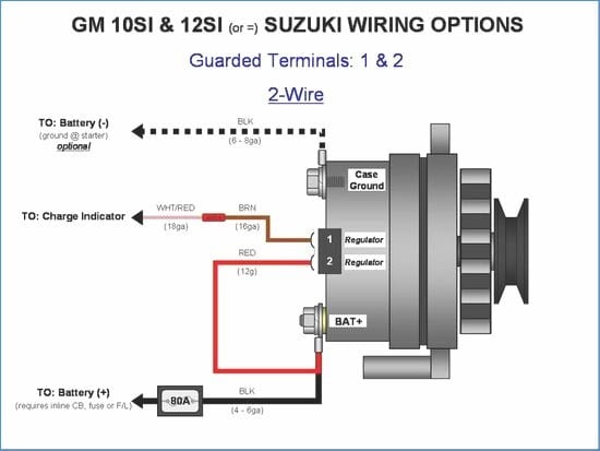
- Battery Terminal (B+): The main output terminal of the alternator, connected directly to the positive (+) terminal of the battery. This is often a large stud.
- Ignition/Exciter Wire (Typically L or #1 Terminal): Provides a small amount of voltage from the ignition switch to "excite" the alternator's internal voltage regulator and rotor, initiating the charging process. This wire is only powered when the ignition is on.
- Ground: The alternator case must be properly grounded to the vehicle chassis to complete the electrical circuit. This is often achieved through the alternator's mounting bracket and a dedicated ground wire.
- Internal Voltage Regulator: Controls the alternator's output voltage to maintain a consistent charging voltage (typically around 13.8-14.4 volts) without overcharging the battery. The 2-wire alternator utilizes an internal regulator for simplified wiring.
Symbols: Decoding the Wiring Diagram
Understanding the symbols in a wiring diagram is crucial for interpreting it correctly. Here's a breakdown of common symbols:
- Solid Lines: Represent wires. The thickness of the line sometimes indicates the wire gauge (thicker lines for higher current capacity).
- Dashed Lines: Often represent shielded cables or grounding connections.
- Colors: Wires are often color-coded to aid in identification. Common colors include red (power), black (ground), and various other colors for signal and control wires. Always consult the specific diagram for your vehicle, as color codes can vary.
- Circles or Ovals: Represent connections or components.
- Rectangles: Often represent electrical components like relays or the alternator itself.
- Ground Symbol: A symbol that resembles an upside-down Christmas tree or a series of descending horizontal lines, indicating a connection to ground (the vehicle chassis).
- Battery Symbol: A series of alternating long and short lines, indicating the positive and negative terminals of the battery.
- Fuse Symbol: Zigzag line in between two points.
On our downloadable diagram, you'll find a key that clearly explains all the symbols and color codes used.
How It Works: The Flow of Electricity
Here's how the 2-wire GM alternator system works:
- When the ignition key is turned to the "on" position, a small voltage is sent through the ignition/exciter wire to the alternator.
- This voltage activates the alternator's internal voltage regulator, which then energizes the rotor (the rotating part of the alternator).
- As the engine starts and the alternator spins, the rotating rotor creates a magnetic field that induces voltage in the stator windings (the stationary part of the alternator).
- The stator windings produce AC (alternating current) voltage, which is then converted to DC (direct current) voltage by the alternator's internal rectifier diodes.
- The DC voltage is then sent out through the battery terminal (B+) wire to charge the battery and power the vehicle's electrical system.
- The internal voltage regulator continuously monitors the battery voltage and adjusts the alternator's output to maintain the proper charging voltage (around 13.8-14.4 volts).
- The alternator case is grounded to the vehicle chassis, providing a return path for the current.
Real-World Use: Basic Troubleshooting Tips
Here are some basic troubleshooting steps you can take using the wiring diagram:
- No Charging: Use a multimeter to check for voltage at the battery terminal (B+) of the alternator with the engine running. If there's no voltage, check the fuse on the ignition wire. Then, verify that the ignition wire has voltage when the ignition is on. If both are present, the alternator itself might be faulty. Also, check the alternator's ground connection.
- Overcharging: If the battery voltage is excessively high (above 14.5 volts), the internal voltage regulator is likely faulty. Replacing the alternator is generally the best course of action.
- Battery Light Stays On: This often indicates a problem with the charging system. Use the wiring diagram to check the continuity of the ignition wire and the B+ wire. Also, check the alternator's ground.
- Wiring Issues: Look for corroded terminals, frayed wires, and loose connections. Clean or replace damaged wiring as needed. Use the wiring diagram to ensure all connections are made correctly.
Always disconnect the battery's negative terminal before working on any electrical components.
Safety: Highlighting Risky Components
Working with automotive electrical systems involves potential risks. Be aware of these safety precautions:
- Battery: The battery can produce explosive gases. Never smoke or work near open flames when working around the battery. Disconnect the negative terminal first and reconnect it last.
- High Current: The alternator and battery cables carry high currents. Avoid short circuits, as they can cause fires or damage electrical components.
- Voltage Spikes: Disconnecting the battery while the engine is running can damage the alternator and other electronic components due to voltage spikes.
- Always Wear Safety Glasses: Protect your eyes from sparks and debris.
- Consult a Professional: If you're not comfortable working with electrical systems, consult a qualified mechanic.
Be cautious when working on or near the alternator. The B+ terminal carries a high current. Avoid short-circuiting it to ground.
By understanding the wiring diagram and taking the necessary safety precautions, you can confidently diagnose and repair your 2-wire GM alternator system. Remember, we have the file ready for download.