Gm Body Control Module Wiring Diagram
So, you're looking to get your hands dirty with your GM vehicle's Body Control Module (BCM) wiring? Smart move! Understanding the BCM and its wiring diagram is invaluable for diagnostics, repairs, and even custom modifications. Think of the BCM as the central nervous system of your car, controlling everything from your lights and wipers to your power windows and door locks. This article will provide a deep dive into GM BCM wiring diagrams, enabling you to confidently tackle electrical projects. We're assuming you have some basic electrical knowledge and are comfortable using a multimeter.
Purpose of the BCM Wiring Diagram
Why bother with a BCM wiring diagram? Several reasons. Primarily, it's your roadmap for understanding the electrical system. It's essential for:
- Troubleshooting Electrical Issues: When something goes haywire – a light that won't turn off, a door lock that refuses to cooperate – the diagram helps you trace the circuit and pinpoint the faulty component.
- Performing Repairs: Replacing a damaged wire or connector? The diagram shows you exactly where it goes and what it connects to.
- Adding Aftermarket Accessories: Installing a new alarm system, remote starter, or upgraded lighting? The diagram helps you identify the correct wires to tap into.
- Understanding Vehicle Functionality: Even if you're not actively working on your car, the diagram provides insights into how different systems interact.
Without it, you're essentially working blind, risking further damage and potentially voiding your warranty (depending on the modification).
Key Specs and Main Parts of a BCM Wiring Diagram
A typical GM BCM wiring diagram will contain a wealth of information. Key elements include:
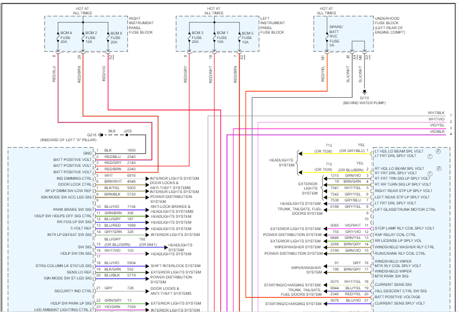
- BCM Connector Views: These show the physical layout of the BCM connectors, with each pin labeled with a number and sometimes a letter. This is crucial for identifying the correct pin to test or connect to.
- Wire Identification: Each wire is usually identified by a color code and a circuit number. For example, "YEL/BLK 1235" might mean a yellow wire with a black stripe, circuit number 1235. Circuit numbers are standardized within GM vehicles to identify a specific circuit.
- Component Symbols: Symbols represent various electrical components like relays, switches, fuses, and sensors. Learning to recognize these symbols is essential for interpreting the diagram.
- Ground Points: These are critical! Diagrams indicate where the circuit grounds to the vehicle's chassis. A bad ground is a common cause of electrical problems.
- Splices: Indicates where multiple wires are joined together. Identifying splice locations is useful for troubleshooting open or short circuits.
- Voltage and Current Ratings: Some diagrams include voltage and current ratings for specific circuits, which is helpful for selecting the correct replacement parts.
You'll also find references to other modules and systems connected to the BCM, showing how they interact.
Decoding the Symbols, Lines, and Colors
The language of a wiring diagram is symbolic. Here's a breakdown of common elements:
- Lines:
- Solid Lines: Represent wires.
- Dashed Lines: Often indicate shielded wires, data lines (like CAN bus), or wires that are part of a harness assembly.
- Thick Lines: May indicate wires with higher current carrying capacity.
- Colors: Each color represents a different wire color. Common abbreviations include:
- BLK: Black
- RED: Red
- WHT: White
- GRN: Green
- BLU: Blue
- YEL: Yellow
- BRN: Brown
- ORG: Orange
- GRY: Gray
- The second color listed indicates a stripe. For example, 'YEL/BLK' is a yellow wire with a black stripe.
- Component Symbols:
- Relay: Often shown as a coil and a set of contacts.
- Switch: Depicted as a contact that opens or closes.
- Fuse: A zig-zag line inside a rectangle. The fuse rating (e.g., 10A) will be indicated nearby.
- Ground: A symbol resembling an inverted triangle or a series of descending lines.
- Resistor: A zig-zag line.
- Capacitor: Two parallel lines.
Understanding these basic symbols and color codes is essential for tracing circuits and diagnosing problems.
How the BCM Works (Simplified)
The BCM is essentially a computer that controls various body functions. It receives input from sensors and switches, processes the information, and then activates outputs to control devices like lights, motors, and solenoids.
Here's a simplified example: You press the power window switch. The switch sends a signal to the BCM. The BCM, based on the switch position, activates a relay that sends power to the window motor. The motor then raises or lowers the window.
The BCM uses programmed logic (software) to make decisions based on these inputs. It also communicates with other modules in the vehicle via a Controller Area Network (CAN) bus, a digital communication network that allows different modules to share information. Understanding this communication is crucial for diagnosing complex problems.
Real-World Use: Basic Troubleshooting Tips
Let's say your interior lights aren't working. Here's how you might use the wiring diagram to troubleshoot:
- Consult the Diagram: Find the section of the wiring diagram that shows the interior lights circuit.
- Identify Key Components: Locate the BCM connector, the fuse for the interior lights, the light switch, and the lights themselves.
- Check the Fuse: Use a multimeter to check if the fuse is blown. If it is, replace it with a fuse of the same amperage rating.
- Test for Voltage: Use a multimeter to check for voltage at the light switch. If there's no voltage, the problem could be the fuse, the wiring between the fuse and the switch, or a faulty BCM output.
- Check the Ground: Make sure the lights have a good ground connection. A poor ground can cause all sorts of strange electrical problems.
- Inspect Wiring: Look for damaged or corroded wires and connectors.
Remember to always disconnect the battery before working on electrical systems! This prevents accidental shorts and potential damage to the vehicle.
Safety Considerations
Working with automotive electrical systems can be dangerous. Here are some crucial safety precautions:
- Disconnect the Battery: Always disconnect the negative battery cable before working on any electrical components. This prevents accidental shorts and potential electrocution.
- Be Aware of High-Current Circuits: Some circuits, like the starter circuit, carry very high currents. Be extremely careful when working with these circuits.
- Use Proper Tools: Use insulated tools and wear appropriate safety gear, such as gloves and eye protection.
- Never Work on a Live Circuit: Unless absolutely necessary for testing, never work on a live circuit.
- Understand Component Function: Before working on any component, understand its function and potential hazards.
- Airbags and SRS Systems: Exercise extreme caution when working near airbags or other Supplemental Restraint System (SRS) components. Improper handling can cause the airbags to deploy, resulting in serious injury. Consult the service manual for proper procedures before working on these systems.
The BCM itself can be a sensitive electronic component. Avoid static electricity when handling it, as it can damage the module.
Accessing the Diagram
We have a comprehensive GM BCM wiring diagram file available for download. This diagram is a valuable resource for diagnosing and repairing electrical issues in your GM vehicle. It contains detailed information about the BCM's connections, circuits, and components. You can download the diagram here: [Insert Download Link Here – Placeholder, needs actual link]. Make sure to select the diagram that corresponds to your specific vehicle year, make, and model. Wiring diagrams can vary significantly between different vehicles.
Remember, this article provides a general overview. Always consult the factory service manual for your specific vehicle for the most accurate and detailed information. With a bit of knowledge, the right tools, and a healthy dose of caution, you can confidently navigate your GM vehicle's BCM wiring diagram and tackle your next electrical project. Good luck!