
Gm Mass Air Flow Sensor Wiring Diagram
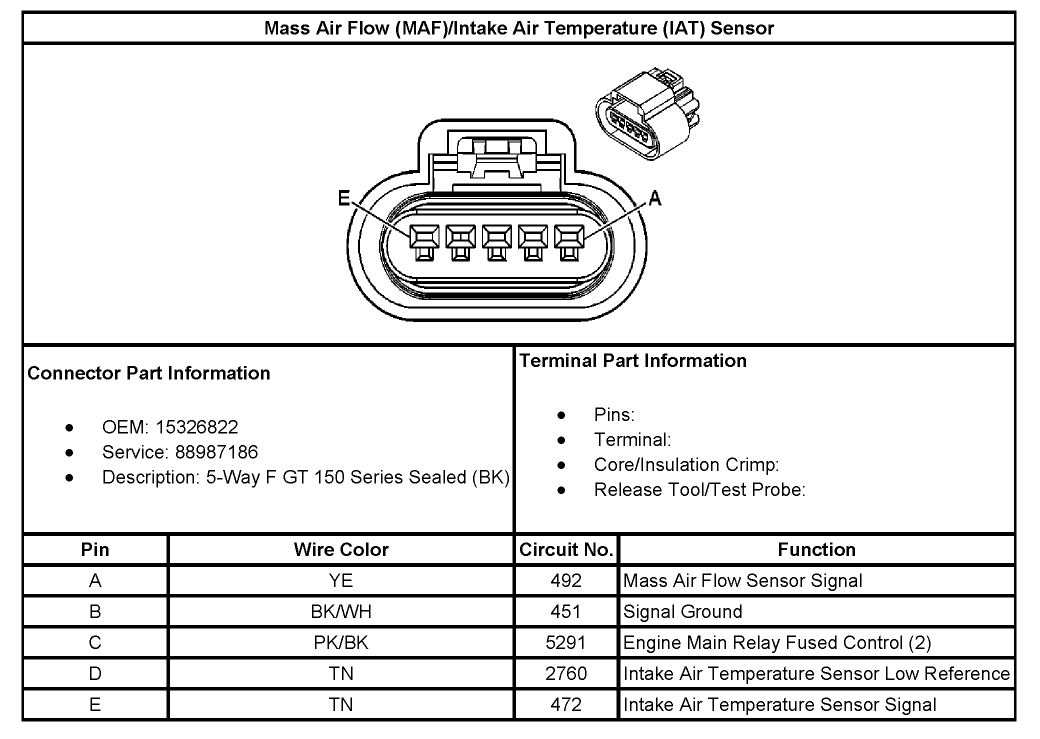
Alright, let's dive into the Gm Mass Air Flow (MAF) sensor wiring diagram. This diagram is your roadmap to understanding, diagnosing, and potentially repairing issues with your vehicle's air intake system. Whether you're chasing down a pesky check engine light, planning an engine modification, or just want to get a deeper understanding of how your car works, understanding the MAF sensor circuit is crucial.
Why Bother with the Wiring Diagram?
Think of the MAF sensor as the gatekeeper of air entering your engine. It measures the mass of air flowing into the engine, a critical piece of information the engine control unit (ECU) uses to calculate the correct amount of fuel to inject. A faulty MAF sensor can lead to a whole host of problems, including:
- Poor fuel economy
- Rough idling
- Hesitation during acceleration
- Stalling
- Check engine light (typically accompanied by codes like P0100, P0101, P0102, P0103)
Having the wiring diagram allows you to:
- Diagnose electrical issues within the MAF sensor circuit.
- Test the integrity of the wiring and connections.
- Understand the role of each wire and component.
- Plan modifications or upgrades that involve the MAF sensor.
Key Specs and Main Parts
Before we dissect the diagram, let's identify the main players and their general specifications. Keep in mind that specific values and wiring configurations can vary depending on the year, make, and model of your GM vehicle.
MAF Sensor
The heart of the system, the MAF sensor typically houses a heated element (hot wire or hot film) that's cooled by the incoming air. The amount of electrical current needed to maintain the element at a constant temperature is directly proportional to the mass of air flowing through it.
Typical Pins and their functions (General):
- Power (12V or 5V): Supplies voltage to the sensor. Crucially, this is often a *reference* voltage from the ECU and should be very stable.
- Ground: Provides a return path for the electrical current. A good, solid ground is essential for accurate readings.
- Signal (MAF Signal): The output signal (voltage) that represents the mass airflow. This is the signal the ECU uses for fuel calculations.
- Intake Air Temperature (IAT) Sensor Signal (Sometimes): Some MAF sensors integrate an IAT sensor, which measures the temperature of the incoming air. This is used to correct for air density changes due to temperature variations.
- Ground for IAT (Sometimes): Ground return for IAT.
Wiring Harness and Connectors
These connect the MAF sensor to the vehicle's electrical system. Check for corrosion, loose connections, and damaged wiring.
Engine Control Unit (ECU)
The brain of the operation. The ECU receives the MAF sensor signal and uses it to calculate the appropriate fuel injection amount, ignition timing, and other engine parameters.
Fuses and Relays
Protect the MAF sensor circuit from overcurrent and control power flow to the sensor. Check the relevant fuses and relays if you suspect a problem.
Decoding the Wiring Diagram: Symbols, Lines, and Colors
Wiring diagrams use standardized symbols and conventions to represent electrical components and connections. Here's a breakdown of common elements:
- Solid Lines: Represent wires. The thickness of the line doesn't usually indicate wire gauge.
- Dashed Lines: May represent shielded wiring or connections to other systems.
- Circles with Numbers: Represent connectors and pin numbers.
- Squares: Can represent switches, relays, or other control devices.
- Resistor Symbol: A zig-zag line represents a resistor (used to limit current or voltage).
- Ground Symbol: Represents a connection to the vehicle's chassis ground.
- Color Codes: Wires are often color-coded (e.g., RED, BLU, GRN, YEL, BLK) to help identify them. The diagram will usually have a key indicating the color abbreviations.
Important: Always refer to the specific wiring diagram for your vehicle. General diagrams are helpful, but can't replace the precise information in the correct diagram.
How the MAF Sensor Circuit Works
Here's a simplified explanation of how the circuit functions:
- The ECU provides power (typically 5V or 12V) and a ground to the MAF sensor.
- Air flows past the heated element in the MAF sensor, cooling it down.
- The sensor's internal circuitry increases the current flowing through the heated element to maintain its temperature at a constant value.
- The amount of current required is proportional to the mass of air flowing through the sensor.
- The MAF sensor generates a voltage signal proportional to the airflow. This signal is sent back to the ECU.
- The ECU uses this signal, along with other sensor inputs (e.g., engine speed, throttle position), to calculate the correct fuel injection amount and ignition timing.
- If the MAF sensor also includes an IAT sensor, it measures the air temperature, and provides this value to the ECU, usually using a thermistor.
Real-World Use: Basic Troubleshooting Tips
Here's how you can use the wiring diagram to troubleshoot MAF sensor issues:
- Visual Inspection: Check for damaged wiring, loose connectors, and corrosion at the MAF sensor and along the wiring harness.
- Voltage Checks: Use a multimeter to check for proper voltage at the MAF sensor power and ground pins. Compare your readings to the specifications in the wiring diagram or service manual. If voltage is absent, trace the power wire back to the fuse box or ECU, checking for breaks or shorts along the way.
- Continuity Checks: Use a multimeter to check for continuity between the MAF sensor ground pin and a known good ground point on the vehicle's chassis. A lack of continuity indicates a ground fault. Also check for continuity along the signal wire back to the ECU connector, in some situations.
- Signal Verification: With the engine running, use a scan tool to monitor the MAF sensor signal. The signal should increase as engine speed and load increase. Compare the readings to expected values based on your vehicle's specifications.
- Component testing: Remove the MAF sensor, and use a multimeter in resistance mode to measure the resistance of the IAT sensor, if present. Compare with expected values.
Safety First!
Working with electrical systems can be dangerous. Always follow these safety precautions:
- Disconnect the Battery: Before working on any electrical components, disconnect the negative battery cable to prevent accidental shocks or short circuits.
- Use Proper Tools: Use insulated tools and wear appropriate safety gear, such as gloves and eye protection.
- Be Careful with Wiring: Avoid piercing or damaging wires, as this can create short circuits or open circuits.
- High-Resistance Testing: If you are testing resistance in a running circuit, double check the acceptable voltage range, or you can damage your multimeter.
The ECU is a sensitive and expensive component, so be extremely cautious when working around it. Incorrect testing procedures or wiring modifications can damage the ECU. Always consult the vehicle's service manual for specific instructions and warnings.
With a solid understanding of the MAF sensor wiring diagram and its associated components, you're well-equipped to diagnose and resolve a variety of issues affecting your vehicle's performance. Remember to always refer to the specific wiring diagram for *your* vehicle's year, make, and model for accurate information.
We have access to a comprehensive database of GM wiring diagrams. If you'd like a copy of the diagram specific to your vehicle, please provide us with the year, make, and model, and we can provide you with a download link.