
Gm One Wire Alternator Wiring Diagram
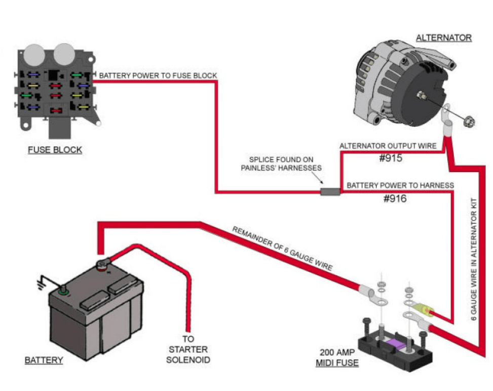
Let's dive into the world of GM one-wire alternator wiring diagrams. This knowledge is invaluable whether you're tackling a classic car restoration, upgrading your charging system, or simply trying to understand how your vehicle's electrical system operates. This guide will break down the diagram, explain the components, and offer some practical troubleshooting tips to keep you running smoothly.
Purpose: Why This Diagram Matters
The GM one-wire alternator wiring diagram is your roadmap for understanding, diagnosing, and repairing the charging system in vehicles equipped with this type of alternator. Unlike older alternators that require multiple wires for voltage regulation and activation, the one-wire system simplifies the installation and wiring process. This makes it popular in modified vehicles, hot rods, and classic car conversions. Understanding the diagram allows you to:
- Troubleshoot Charging Issues: Quickly identify potential faults like a non-charging alternator, overcharging, or a parasitic draw.
- Perform Upgrades: Safely install a higher-output alternator or modify the wiring for improved performance.
- Understand Electrical Systems: Gain a deeper understanding of automotive electrical systems and how they interact.
- Perform Repairs: Make necessary repairs to the wiring or replace components with confidence.
Key Specs and Main Parts
Before we delve into the specifics of the diagram, let's familiarize ourselves with the key components involved in a typical GM one-wire alternator system:
- Alternator: The heart of the charging system, responsible for converting mechanical energy from the engine into electrical energy. Specifically, it's a self-exciting, internally regulated alternator. This means it doesn't require an external voltage regulator or a separate excitation wire.
- Battery: Provides the initial power to start the engine and stores electrical energy generated by the alternator. A healthy battery is crucial for the proper operation of the charging system.
- Battery Cables: Heavy-gauge cables that connect the battery to the vehicle's electrical system. These cables must be in good condition to ensure proper current flow.
- Fusible Link (or Fuse): A safety device designed to protect the wiring from overcurrent. It's usually located near the battery and is the first line of defense against shorts and electrical fires.
- Ground Connection: A crucial connection that provides a return path for current flow. A good ground is essential for proper system operation. Engine block to chassis ground is very important.
Here are some key specs to be aware of:
- Voltage Output: Typically 13.8 - 14.4 volts. This range is critical for charging the battery without damaging it.
- Current Output: Varies depending on the alternator model, ranging from 60 amps to over 100 amps. Choose an alternator with sufficient output for your vehicle's electrical demands.
- Wire Gauge: The wire gauge is critical for handling the high current output of the alternator. Using too small a wire can lead to overheating and voltage drop. 8 or 10 gauge wire is generally sufficient for the main charging wire.
Symbols – Understanding the Diagram
Automotive wiring diagrams use standardized symbols to represent electrical components and connections. Here's a breakdown of some common symbols you'll encounter in a GM one-wire alternator diagram:
- Straight Lines: Represent wires or conductors. Thicker lines indicate larger gauge wires.
- Dotted Lines: Often indicate ground connections.
- Battery Symbol: A series of short and long parallel lines, representing the battery's positive and negative terminals.
- Alternator Symbol: A circle with the letter "A" inside. Sometimes it includes additional symbols indicating the type of alternator.
- Fuse/Fusible Link Symbol: A wavy line or a rectangle with a diagonal line through it.
- Ground Symbol: A series of horizontal lines, decreasing in length.
Color Coding: Wire colors are also significant. While there's no universal standard, common colors include:
- Red: Typically used for positive (+) connections, especially the main charging wire from the alternator to the battery.
- Black: Generally used for ground (-) connections.
- Other colors (e.g., Blue, Green, Yellow) may be used for other circuits, but their function will be indicated in the diagram's legend.
It's essential to refer to the specific diagram for your vehicle or alternator model, as color coding and component placement can vary.
How It Works
The one-wire alternator system is relatively simple in operation. Here's a step-by-step explanation:
- Initial Excitation: When the engine starts, the alternator relies on residual magnetism in its rotor to generate a small amount of voltage. This initial voltage is enough to "excite" the alternator and start the charging process.
- Voltage Build-Up: As the alternator spins faster, it generates more voltage and current. The internal voltage regulator monitors the output voltage and adjusts the field current to maintain a stable charging voltage (typically around 14 volts).
- Charging the Battery: The alternator's output voltage is connected directly to the battery's positive terminal through a heavy-gauge wire. This allows the alternator to charge the battery and supply power to the vehicle's electrical system.
- Voltage Regulation: The internal voltage regulator prevents the alternator from overcharging the battery. It continuously monitors the voltage and adjusts the field current to maintain the desired output voltage.
The "one wire" aspect refers to the fact that only one wire (besides the ground) is needed to connect the alternator to the battery. This simplifies the wiring process compared to older systems that require separate wires for voltage sensing and activation.
Real-World Use – Basic Troubleshooting Tips
Here are some basic troubleshooting tips for diagnosing problems with a GM one-wire alternator system:
- No Charging: If the alternator isn't charging, check the following:
- Battery Voltage: Ensure the battery is in good condition and has sufficient charge. A completely dead battery may not be able to excite the alternator.
- Main Charging Wire: Inspect the wire connecting the alternator to the battery for damage, corrosion, or loose connections. Use a multimeter to check for voltage at the alternator's output terminal when the engine is running.
- Ground Connection: Verify that the alternator is properly grounded to the engine block and that the engine block is properly grounded to the chassis. A poor ground can prevent the alternator from charging.
- Alternator Condition: If the wiring and connections are good, the alternator itself may be faulty. Consider having it tested at an auto parts store.
- Overcharging: If the alternator is overcharging (voltage above 14.5 volts), the internal voltage regulator is likely faulty. Replace the alternator.
- Voltage Drop: If the voltage at the battery is significantly lower than the voltage at the alternator's output terminal, there may be excessive voltage drop in the wiring. Check for corrosion, loose connections, and undersized wiring. Upgrade the wiring if necessary.
Safety – Highlight Risky Components
Working with automotive electrical systems can be dangerous. Here are some safety precautions to keep in mind:
- Disconnect the Battery: Always disconnect the negative battery cable before working on the electrical system. This will prevent accidental shorts and electrical shocks.
- Use Proper Tools: Use insulated tools designed for automotive electrical work.
- Wear Safety Glasses: Protect your eyes from sparks and debris.
- Be Careful with the Alternator: The alternator can generate high voltages and currents. Avoid touching the terminals while the engine is running.
- Fusible Links/Fuses: Always replace a blown fuse or fusible link with one of the same rating. Using a higher-rated fuse can overload the wiring and create a fire hazard.
- Avoid Water: Never work on electrical systems in wet conditions.
The alternator itself can present a few risks. Touching the output terminal with the engine running can deliver a significant electrical shock. Always disconnect the battery before handling the alternator or its wiring.
By understanding the GM one-wire alternator wiring diagram and following these safety precautions, you can confidently diagnose and repair charging system problems on your vehicle. With a little patience and the right tools, you'll be back on the road in no time.
We have a downloadable PDF file containing a typical GM one-wire alternator wiring diagram. This file can be zoomed, printed, and used in your shop. You can request the file to be sent to you.