
Gm Single Wire Alternator Wiring Diagram
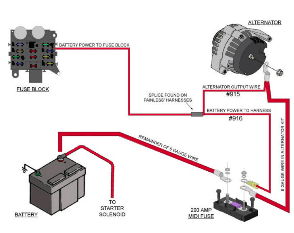
The General Motors (GM) single-wire alternator wiring diagram is an invaluable resource for anyone working on older GM vehicles, hot rods, or custom builds where electrical simplicity is desired. Understanding this diagram allows you to diagnose charging issues, perform repairs, and even retrofit a single-wire alternator into a vehicle that wasn't originally equipped with one. Forget chasing multiple wires and complex voltage regulator setups; the single-wire setup offers a cleaner, simpler approach.
Purpose of Understanding the Wiring Diagram
Why bother learning about this diagram? Several reasons:
- Troubleshooting: When your battery isn't charging, the single-wire setup, while simple, can still fail. The diagram guides you in tracing the single wire to check for breaks, shorts, or a faulty alternator.
- Retrofitting: Swapping an older multi-wire alternator for a single-wire unit can simplify your wiring harness and clean up the engine bay. The diagram clarifies the necessary connections.
- Custom Builds: For hot rods, custom cars, and off-road vehicles, a clean, reliable charging system is crucial. The single-wire alternator, properly installed using the diagram, offers just that.
- Education: Gaining a deeper understanding of automotive electrical systems is always beneficial. Studying this diagram helps you grasp basic alternator functionality and wiring principles.
Key Specs and Main Parts of the Single-Wire Alternator System
The heart of this system is, of course, the single-wire alternator. Understanding its components and specifications is essential:
- Alternator: The component that converts mechanical energy from the engine into electrical energy to charge the battery and power the vehicle's electrical system. Look for the output amperage rating (e.g., 63 amp, 100 amp). A higher amperage rating allows it to power more accessories.
- Single Wire: This is the heavy-gauge wire (typically 8 or 10 gauge) that connects the alternator's output terminal directly to the battery's positive (+) terminal (or a suitable distribution block tied directly to the battery). It carries the charging current.
- Battery: Stores electrical energy and provides power to start the engine and operate electrical accessories when the engine isn't running.
- Ground Wire: While it's called single-wire, the alternator *must* be properly grounded to the engine block. This is typically achieved through the alternator's mounting bracket or a separate ground wire. A good ground is crucial for proper operation!
- Voltage Regulator (Internal): Single-wire alternators have an internal voltage regulator. This component maintains a consistent voltage output (typically around 14.4 volts) to prevent overcharging the battery. The regulator is pre-set and requires no external adjustments.
Understanding the Wiring Diagram Symbols
A wiring diagram uses standard symbols to represent electrical components and connections. Here's a breakdown of common symbols you'll encounter:
- Solid Lines: Represent wires. The thickness of the line can sometimes indicate the wire gauge (thicker lines for thicker wires).
- Dotted Lines: May indicate shielded wires or wires that are part of a larger harness and not directly connected in the immediate circuit.
- Battery Symbol: A series of alternating long and short parallel lines, usually labeled "+" and "-".
- Alternator Symbol: Varies, but often a circle with an "A" inside or a stylized representation of the alternator's windings. The single-wire connection is typically shown as a bold line exiting the alternator symbol.
- Ground Symbol: Three horizontal lines decreasing in length, connected vertically. This indicates a connection to ground (the vehicle's chassis).
- Numbers/Letters: Often found next to wires to indicate wire gauge, color code, or circuit identification.
- Color Codes: Wires are often color-coded (e.g., Red for positive, Black for ground). The diagram will usually include a legend to explain the color codes.
Important: Wiring diagrams can vary slightly in their representation of components. The key is to understand the underlying principles and trace the connections logically.
How the Single-Wire Alternator System Works
The single-wire alternator system simplifies the charging process:
- Engine Start: When you start the engine, the alternator begins to spin.
- Voltage Build-Up: The internal voltage regulator requires a certain RPM (revolutions per minute) to initially 'excite' the alternator. This is why some single-wire alternators may require a brief 'rev' of the engine after installation.
- Charging: Once excited, the alternator generates electrical current. This current flows through the single wire directly to the battery's positive terminal.
- Voltage Regulation: The internal voltage regulator monitors the battery's voltage. If the voltage is low, the regulator allows the alternator to generate more current. If the voltage is high, the regulator reduces the current output to prevent overcharging.
- Grounding: The alternator is grounded to the engine block (and thus to the vehicle's chassis), completing the electrical circuit.
Real-World Use: Basic Troubleshooting Tips
Here are some basic troubleshooting tips for a single-wire alternator system:
- No Charge: If the battery isn't charging, first check the single wire for continuity (using a multimeter) between the alternator and the battery. Look for breaks, loose connections, or corrosion.
- Poor Ground: A bad ground can cause all sorts of problems. Ensure the alternator is securely mounted to the engine block and that the engine block is properly grounded to the chassis. You can add a separate ground wire from the alternator case to the chassis as an extra measure.
- Overcharging: If the battery is overcharging (boiling, emitting fumes), the internal voltage regulator is likely faulty. The alternator will need to be replaced.
- Initial Excitation Issues: If the alternator doesn't start charging immediately after starting the engine, try giving the engine a brief rev. If this consistently solves the problem, you may have an alternator that requires a higher RPM for initial excitation.
- Voltage Drop Test: Perform a voltage drop test on the single wire and the ground wire. Excessive voltage drop indicates resistance in the circuit, which can reduce charging efficiency.
Safety Considerations
Working with automotive electrical systems can be dangerous. Keep these safety tips in mind:
- Disconnect the Battery: Always disconnect the battery's negative (-) terminal before working on any electrical components. This prevents accidental shorts and electrical shocks.
- Insulated Tools: Use insulated tools to prevent shorts and electrical shocks.
- Proper Wire Gauge: Use the correct gauge wire for the single-wire connection. A wire that is too small can overheat and cause a fire. Use at least 8 gauge wire, and 6 gauge is preferable for higher amperage alternators.
- Fusing (Optional but Recommended): While not strictly part of the basic single-wire setup, consider adding a fuse or fusible link to the single wire near the battery. This protects the system from overloads and shorts.
- Avoid Water: Never work on electrical systems in wet conditions.
Remember that alternators have large capacitors that can hold a charge even after the battery is disconnected. While not generally dangerous, avoid touching the terminals immediately after disconnection.
We've Got the Diagram – Ready to Download!
This article provides a solid foundation for understanding the GM single-wire alternator wiring diagram. To further enhance your knowledge and ensure accurate wiring, a detailed diagram is essential. We have a comprehensive, downloadable diagram available that you can use as a reference for your projects and repairs. This diagram includes clear labeling, color-coded wiring, and detailed component illustrations.
We have the file available for download to help you get your project done right. Happy wrenching!