Gm Steering Column Wiring Connectors
The General Motors (GM) steering column wiring harness is a critical component for a multitude of vehicle functions. Understanding its configuration, wiring diagrams, and connectors is essential for accurate diagnosis, repairs, modifications, and even advanced diagnostics. This article will provide a detailed breakdown of GM steering column wiring connectors, empowering you to confidently tackle related projects.
Purpose: Why This Knowledge Matters
Why should you bother understanding the intricacies of your GM steering column wiring? There are several compelling reasons:
- Repair and Restoration: Damaged wires or corroded connectors are common culprits behind malfunctions in turn signals, wipers, cruise control, and other systems integrated into the steering column. Knowing the wiring layout is essential for identifying and repairing these issues.
- Aftermarket Modifications: Installing aftermarket accessories, like remote starters or performance steering wheels, often requires tapping into the existing steering column wiring. A solid understanding prevents miswiring, which can lead to electrical damage.
- Troubleshooting Electrical Issues: When other diagnostic procedures fail, tracing circuits through the steering column can pinpoint the root cause of electrical problems affecting various vehicle systems.
- Learning and Expanding Your Skills: Even if you're not currently facing an issue, familiarizing yourself with the steering column wiring expands your automotive knowledge and enhances your DIY capabilities.
Key Specs and Main Parts
GM steering columns, while appearing similar across models and years, exhibit significant variations in wiring configurations. Key specifications include:
- Model Year: Wiring changed significantly over the decades. A wiring diagram for a 1985 Chevrolet C10 will be drastically different from one for a 2015 GMC Sierra.
- Vehicle Trim Level: Higher trim levels often include more features integrated into the steering column, such as heated steering wheels, tilt/telescoping columns, and advanced driver-assistance systems (ADAS) controls. This translates to more complex wiring.
- Column Type: Standard, tilt, or tilt/telescoping columns affect the placement and routing of wiring, as well as the connector types used.
- Connector Pin Count: The number of pins in each connector is a direct indicator of the number of functions controlled through the column.
The main parts associated with the steering column wiring system include:
- Connectors: These are the interface points for different circuits. Common types include multi-pin connectors for bundled wires, single-wire connectors for specific functions, and inline connectors for splicing.
- Wiring Harness: The bundle of wires that carries electrical signals to and from various components in the steering column.
- Turn Signal Switch: Controls turn signals, hazard lights, and often the high beam headlights.
- Wiper Switch: Operates the windshield wipers and washer fluid pump.
- Ignition Switch: Controls the vehicle's power, starting, and accessory circuits.
- Cruise Control Switch: If equipped, controls the cruise control system.
- Airbag Clockspring: A coiled ribbon cable that maintains a continuous electrical connection to the airbag module in the steering wheel, even as the wheel rotates. This is a critical safety component.
Symbols: Understanding Wiring Diagrams
Wiring diagrams use standardized symbols to represent electrical components and connections. Familiarity with these symbols is crucial for interpreting diagrams correctly.
- Solid Lines: Represent wires. The thickness of the line doesn't usually indicate wire gauge unless specified.
- Dashed Lines: Often represent shielded wires or ground connections.
- Circles: Typically indicate connectors or terminals. Numbered circles usually correspond to pin numbers on the connector.
- Squares: Can represent switches, relays, or electronic modules.
- Resistors: Represented by a zig-zag line.
- Ground Symbol: Indicates a connection to the vehicle's chassis ground.
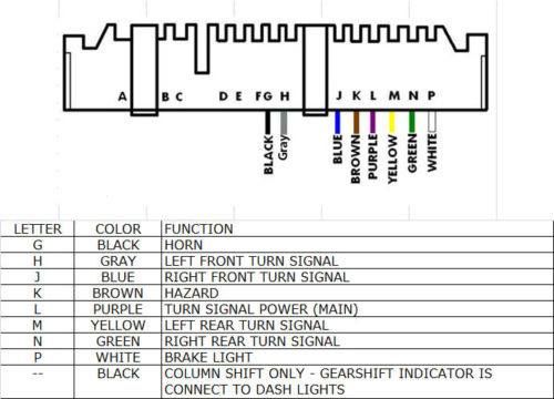
- Color Codes: Wires are often identified by color codes (e.g., BLK for black, RED for red, WHT for white). Combinations like "WHT/BLK" indicate a white wire with a black stripe.
- Icons: Specific icons are used to represent components like lamps, motors, and sensors. These icons vary, so refer to the diagram's legend for clarification.
Understanding wire color abbreviations is essential. Some common ones include: BLK (Black), BRN (Brown), RED (Red), ORN (Orange), YEL (Yellow), GRN (Green), BLU (Blue), PUR (Purple), GRY (Gray), WHT (White), PNK (Pink), TAN (Tan). Combinations (e.g., BLK/WHT) indicate a wire with a base color and a stripe color.
How It Works: Signal Flow
The steering column wiring harness acts as a central hub for various electrical signals. Here's a simplified overview of how it works:
- Power Distribution: The ignition switch controls the flow of power to different circuits based on the key position (OFF, ACC, RUN, START). These circuits feed power to components like the turn signal switch, wiper switch, and cruise control module.
- Switch Activation: When you activate a switch (e.g., turn signal), it completes a circuit, sending a signal to the relevant component (e.g., turn signal lamps).
- Signal Transmission: Wires within the harness carry these signals to their destinations, such as the body control module (BCM) or directly to the controlled devices.
- Grounding: Completing the electrical circuit requires a ground connection. Most components are grounded to the vehicle's chassis through dedicated ground wires.
- Airbag Clockspring Function: The airbag clockspring allows the steering wheel to rotate while maintaining a constant electrical connection to the airbag module. This is achieved through a flat, coiled ribbon cable that unwinds and rewinds as the wheel turns.
Real-World Use: Basic Troubleshooting Tips
Here are some basic troubleshooting tips for common issues related to steering column wiring:
- No Turn Signals: Check the turn signal switch, the flasher relay, and the bulbs. Use a multimeter to test for power at the switch and the bulbs. If the bulbs and relay are good, the switch is the most likely culprit.
- Wipers Not Working: Check the wiper motor fuse, the wiper switch, and the wiper motor itself. A faulty wiper switch or a corroded connector can prevent the wipers from functioning.
- Cruise Control Issues: Check the cruise control switch, the brake light switch (which disengages cruise control), and the vehicle speed sensor. A broken wire or a faulty switch can disable the cruise control system.
- Intermittent Problems: Intermittent problems often indicate loose connections or damaged wires. Carefully inspect the wiring harness for signs of wear, corrosion, or breaks. Use a contact cleaner to clean connectors.
- Airbag Light On: An illuminated airbag light requires professional diagnosis. Do NOT attempt to repair airbag components yourself. Airbag systems are highly sensitive and can deploy unexpectedly, causing serious injury.
When troubleshooting, always refer to a wiring diagram specific to your vehicle's year, make, and model. Generic diagrams may not accurately reflect the wiring configuration of your specific vehicle.
Safety: Proceed with Caution
Working with automotive electrical systems can be dangerous. Here are some safety precautions to keep in mind:
- Disconnect the Battery: Always disconnect the negative battery cable before working on any electrical component. This prevents accidental shorts and electrical shocks.
- Airbag Systems: As mentioned previously, airbag systems are extremely sensitive. Do not attempt to repair or modify airbag components unless you are a qualified technician. Improper handling can cause accidental deployment, resulting in serious injury. If you suspect an airbag issue, take your vehicle to a professional.
- Use Proper Tools: Use insulated tools to prevent electrical shocks. A multimeter is essential for testing circuits safely.
- Follow Wiring Diagrams: Always refer to a wiring diagram specific to your vehicle. Miswiring can damage electrical components or create safety hazards.
- Don't Cut Wires Unnecessarily: Only cut wires when absolutely necessary. Use proper splicing techniques to ensure secure and reliable connections.
By understanding the GM steering column wiring connectors and adhering to proper safety procedures, you can confidently tackle a range of automotive electrical projects. Remember to consult your vehicle's specific wiring diagrams for accurate information.
We have a detailed GM steering column wiring diagram file available for download. This comprehensive diagram will provide you with the detailed information you need to diagnose and repair issues with your steering column wiring system. Contact us to receive the file.