Gm Wiring Diagrams Pdf Free Download
Wiring diagrams are the unsung heroes of automotive repair and modification. A General Motors (GM) wiring diagram, in particular, is an invaluable resource for anyone working on a GM vehicle, whether it's a vintage classic or a modern marvel. This guide explains the importance of GM wiring diagrams, how to understand them, and how to safely use them for troubleshooting and modifications.
Purpose of a GM Wiring Diagram
Why bother with a wiring diagram? The primary purpose is to provide a visual representation of the electrical system. It's a roadmap that shows you how components are connected, allowing you to:
- Troubleshoot Electrical Problems: Identify shorts, opens, and other faults in the wiring harness.
- Perform Repairs: Locate damaged wires or components and replace them correctly.
- Install Aftermarket Accessories: Properly wire in new stereos, lights, or other electrical devices.
- Understand Vehicle Systems: Gain a deeper understanding of how the electrical systems work together.
- Modify Your Vehicle: Safely and effectively alter the electrical system for performance or cosmetic enhancements.
Key Specs and Main Parts of a GM Wiring Diagram
A GM wiring diagram isn't just a bunch of squiggly lines. It contains specific information laid out in a standardized format.
- Vehicle Year and Model: Diagrams are specific to a particular year and model due to variations in electrical systems. Always ensure you have the correct diagram for your vehicle.
- System Identification: The diagram will typically focus on a specific system, such as the starting system, charging system, lighting system, or engine management system.
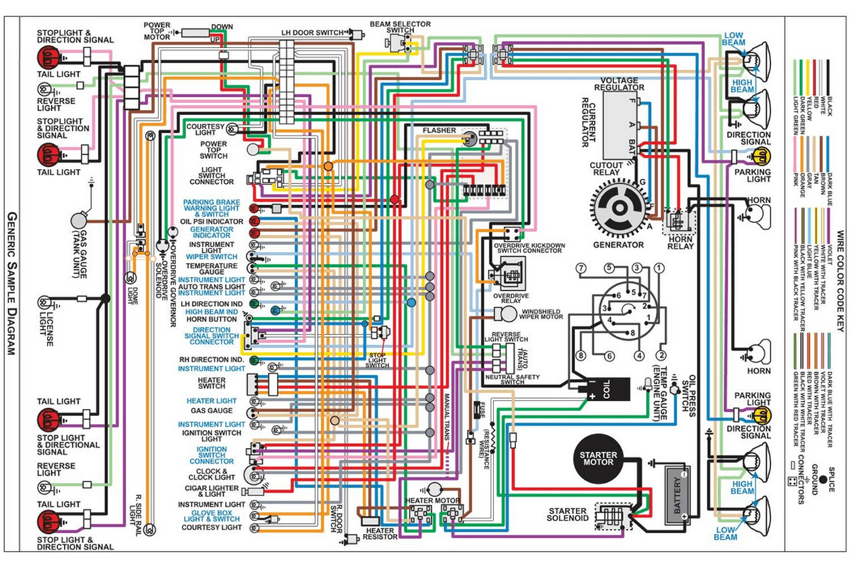
- Component Symbols: Each electrical component (e.g., relays, switches, fuses, sensors, motors) is represented by a unique symbol.
- Wire Numbers and Colors: Wires are identified by a number or code and a color. This helps you trace wires throughout the harness.
- Ground Points: Ground points are indicated by a specific symbol and are crucial for ensuring proper circuit completion.
- Connectors: Connectors are shown as blocks or circles with pin numbers. These indicate where wires connect to each other.
- Fuses and Relays: Fuses and relays are represented by their own symbols and amperage ratings. These are critical for circuit protection and control.
- Voltage Values: Some diagrams may include voltage values at specific points in the circuit to aid in troubleshooting.
Understanding Symbols, Lines, and Colors
Deciphering the symbols, lines, and colors is essential for reading a GM wiring diagram:
- Lines: Solid lines represent wires. Dashed lines may represent shielded wires or connections between multiple diagrams. The thickness of the line doesn't represent wire gauge, but rather visibility.
- Colors: Each wire color is represented by a code, usually a two- or three-letter abbreviation (e.g., BLU for blue, RED for red, GRN for green). Some diagrams use full names. Understanding these abbreviations is crucial.
- Component Symbols: These vary depending on the component. Common symbols include:
- Resistors: A zigzag line.
- Capacitors: Two parallel lines.
- Diodes: A triangle pointing to a vertical line.
- Switches: A line connecting or disconnecting from another line. The type of switch (e.g., SPST, SPDT, DPST) will be indicated.
- Relays: A coil symbol with switch contacts.
- Fuses: A wavy line inside a rectangle.
- Grounds: A series of descending horizontal lines.
Consult the diagram's legend or key for a complete list of symbols and color codes.
How It Works: Tracing a Circuit
The key to using a wiring diagram effectively is to trace the circuit you're interested in. Here's a step-by-step guide:
- Identify the Circuit: Determine the system you want to investigate (e.g., headlights, starter motor).
- Locate the Diagram: Find the wiring diagram for that specific system in the service manual or online resource.
- Identify the Power Source: Locate the power source (e.g., battery, ignition switch) for the circuit.
- Follow the Path: Trace the wire from the power source to the first component (e.g., a fuse). Pay attention to wire colors and numbers.
- Continue Tracing: Follow the wire through each component in the circuit (e.g., switch, relay, motor).
- Locate the Ground: Trace the wire from the last component back to the ground point.
- Understand the Flow: As you trace the circuit, visualize how electricity flows through each component, enabling it to function.
By carefully tracing the circuit, you can identify potential points of failure and understand how each component contributes to the overall function.
Real-World Use: Basic Troubleshooting Tips
Wiring diagrams are incredibly useful for troubleshooting. Here are some basic tips:
- No Power: If a component isn't working, use the diagram to check if it's receiving power. Use a multimeter to test voltage at the component's terminals.
- Ground Issues: A bad ground can cause all sorts of problems. Use the diagram to locate the ground point and check for corrosion or loose connections.
- Short Circuits: A short circuit occurs when a wire accidentally connects to ground. The diagram can help you identify potential areas where wires might be damaged or pinched. Fuses blowing repeatedly are a strong indicator of a short.
- Open Circuits: An open circuit occurs when a wire is broken or disconnected. Use the diagram to trace the circuit and look for breaks in the wire or loose connections.
- Component Failure: The diagram can help you isolate a faulty component. By testing the voltage and continuity at the component's terminals, you can determine if it's functioning correctly.
Example: Let's say your headlights aren't working. Consult the headlight wiring diagram. First, check the fuse. If the fuse is blown, replace it and see if it blows again. If it does, you likely have a short circuit. If the fuse is good, use a multimeter to check for voltage at the headlight switch. If there's no voltage, the switch may be faulty. If there is voltage, trace the wires from the switch to the headlights, looking for breaks or loose connections. Check the ground connection for the headlights as well.
Safety Considerations
Working with automotive electrical systems can be dangerous. Always take these precautions:
- Disconnect the Battery: Before working on any electrical system, disconnect the negative battery cable to prevent accidental shorts or shocks.
- Use Proper Tools: Use insulated tools designed for automotive electrical work.
- Be Aware of Airbags: Airbag systems contain capacitors that can store a charge even after the battery is disconnected. Follow the vehicle manufacturer's instructions for disabling the airbag system before working near any airbag components.
- Identify High-Voltage Components: In hybrid and electric vehicles, be extremely cautious of high-voltage components. These are usually marked with warning labels. Only qualified technicians should work on high-voltage systems.
- Read the Diagram Carefully: Take your time and understand the diagram before starting any work.
Always prioritize safety. If you're not comfortable working on electrical systems, consult a qualified mechanic.
Download Your GM Wiring Diagram (PDF)
Having a readily accessible GM wiring diagram in PDF format is essential for convenient reference. We have the specific wiring diagram for your [Vehicle Year] [Vehicle Model] available for download. This diagram will provide you with the detailed information needed for troubleshooting, repairs, and modifications.
Use it wisely, and always prioritize safety!